ISSN ONLINE(2319-8753)PRINT(2347-6710)
ISSN ONLINE(2319-8753)PRINT(2347-6710)
Nilesh R. Mate1, Prof. D. Y. Dhande2
|
| Related article at Pubmed, Scholar Google |
Visit for more related articles at International Journal of Innovative Research in Science, Engineering and Technology
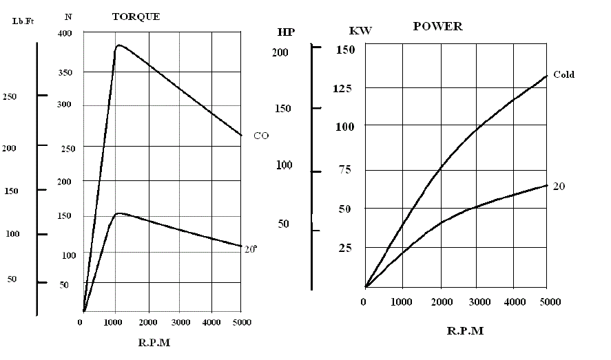
In this study a compact system carrying the eddy current retarder used for the testing of two wheel vehicles is designed. A braking torque of the eddy current retarder is 400 N-m at a speed of 1200 rpm. According to the characteristics of the eddy current retarder, an exclusive test bed was developed and used for brake performance measurements. The main technical parameters, such as the brake characteristics, temperature characteristics and power consumption, were measured with the test bed. Major focus area in this paper is for study of brake characteristics. By observing the torque v/s rpm curve the torque increases initially and reached maximum value at rated or design condition and then torque starts decreasing as rpm increases further. A roller is provided at rear wheel of vehicle and front wheel is properly restrained in clamps to avoid the movement of vehicle.
Keywords |
| Dynamometer, Retarder, Two Wheeler. |
INTRODUCTION |
| One of the toughest conditions for maintenance manager or field service engineer has to face driver’s complaints of low power. In such situation two wheeler vehicle, these complaints result in dynamometer tests to see whether the engine output is within specification. Eddy current dynamometers are electromagnetic load devices. The engine being tested spins a disk in the dynamometer. Electrical current passes through coils surrounding the disk, and induce a magnetic resistance to the motion of the disk. Varying the current varies the load on the engine. In two wheeler vehicles the testing is required to be carried out to check the actual performance with the design performance. Particularly in the service workshops two wheeler is required to run on road and then the problem areas can be find out. If the vehicle is run on the chassis dynamometer the in house problem finding and comparing with the standard requirement is possible. |
II DESIGN REQUIREMENTS |
| The design of the two wheeler dynamometer is basically being focused on the testing and tuning of the two wheeler. The dynamometer must be capable of simulating road load and of one of the following classifications: Dynamometer with fixed load curve, i.e., a dynamometer whose physical characteristics provide a fixed load curve shape. This is not a preferred type of dynamometer. Dynamometer with adjustable load curve, i.e. a dynamometer with at least two road load parameters that can be adjusted to shape the load curve. This is a preferred type of dynamometer. |
III STEPS OF DESIGN PROCEDURE |
| Selection of the range of two wheelers with their power and torque requirements. This information gathered from the different vehicles specifications. |
| - The selection of the dynamometer (retarder) is based on the range of two wheelers torque/power requirements. |
| The type of retarder is selected considering the compactness of the system. As Eddy Current type retarder does not requires any external system for functioning like Hydraulic dynamometer etc. |
| The design of the platform done on the basis of weight of vehicle, forces generated due to inertia, dynamic forces under test. |
| Selection of material for the system is considering the dynamic forces. |
IV DIFFERENT PARTS OF THE SYSTEM |
| 1. Eddy current Retarder |
| 2. Platforma |
| 3. Retarder mounting assembly |
| 4. Roller assembly |
| 5. Data acquisition and Display unit |
IV. I SELECTION OF THE EDDY CURRENT RETARDER |
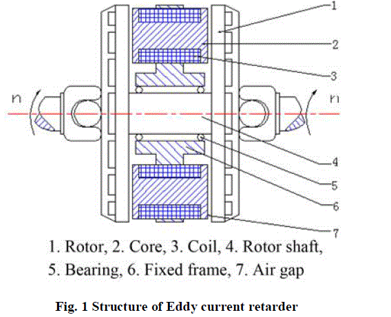
| Eddy current retarder is the core unit of this system and the major selection has been done on the basis of type of two wheeler to be tested. Air-cooled eddy current power absorber is researched and developed based on the need of automobile inspection test equipment, and its main application is in the motorcycle chassis dynamometer, chassis dynamometer, emissions loading equipment, automotive test stand and the presentation of teaching instruments used as a load and torque measurement. Following are the parameters considered while selecting the retarder: - Power requirement of two wheeler - Torque requirement of two wheeler - Maximum speed - Size of system An eddy current retarder is made up of eight cores, an air gap, coils and rotor plates, as shown in Figure 1. |
 |
| A coil is installed on the cylindrical surface of a core. The coil creates the windings. There is an even number of windings, and they are distributed equally around the circumference of the core. When the windings of the eddy current retarder are electrified, the kinetic or potential energy of the automobile can be transformed into thermal energy and dissipated into the atmosphere by a wind tunnel cast in the rotor plate, according to the electromagnetic principle. When a driver turns the control handle for deceleration or braking, the windings of the eddy current retarder are electrified automatically. As a result, the magnetic line among the field stator poles, the air gap, and the front and rear rotor plate constitutes a loop. |
IV. II DESIGN OF PLATFORM |
| Platform is the structure which withstands the all loads generated by the vehicle dynamics as well as retarder forces. The major design considerations for the platform are as follows: - Weight of two wheeler and rider - Rotating forces generated by retarder - Space optimization (compactness) The design of platform is taken in to consideration of compactness of the system as well as the future scope different system addition in the same unit. |
IV. III RETARDER MOUNTING ASSEMBLY |
| This subassembly is carrying all loads exerted on retarder and reactions generated by it. The mounting assembly is selected a material of mild steel with high strength. This mounting assembly is placed at side of roller and hence the extension shaft is provided to connect the eddy current retarder shaft with the roller shaft on platform. |
IV.IV DATA ACQUISITION AND DISPLAY UNIT |
| A extremely efficient system is useless without some kind of data acquisition system and display unit. This unit measures torque, rpm, fuel flow etc. The goal of a dynamometer and data acquisition system is to produce accurate and repeatable data so that any changes made to the engine or power train can be measured and recorded. In order to test the engine it is generally necessary to use a dynamometer controller. This is usually an electronic unit which has the capability of controlling the load on the dynamometer (i.e. it controls the current to the resistance coils in an eddy current dynamometer) and can measure or sense the load and speed. Dynamometer controllers generally operate in two modes: Speed Controlled operation or Load Controlled operation. In Speed Controlled mode a set speed is given to the controller (either as a voltage or a setting on the front panel of the controller, see figure 2). If the measured speed of the shaft is less than that of the set speed, the load is decreased. If the measured speed of the shaft is greater than that of the set speed, then the load is increased. Assuming the engine has sufficient torque to attain the set speed, this will maintain a constant speed. In Load Controlled mode a set load is given to the controller (either as a voltage or a setting on the front panel of the controller). If the measured load on the dynamometer is greater than that of the set load, the load is decreased. If the measured load on the dynamometer is less than that of the set load, then the load is increased. Assuming the engine has sufficient torque to attain the set load; this will maintain a constant load while the speed varies. |
V. WORKING AND RESULTS |
| In this paper the braking torque of eddy current retarder is 400 N-m at 1200 rpm Adjust the tyre pressure (cold) of the driving wheels as required by the chassis dynamometer. Adjust the equivalent inertia of the chassis dynamometer. Bring the vehicle and chassis dynamometer to operating temperature in a suitable manner. ENGINE TESTING: DRIVE CYCLE To test an engine in a simulated drive cycle it may be best to use the load controlled mode. Generally both the engine speed and load will vary as a function of time, so the dynamometer controller needs to be programmable, or have a load control voltage sent to it from a programmable voltage source (i.e. DAC). Typically a human operator is given the “speed schedule” (i.e. the speed versus time) of the test, and can view the actual speed of the engine. His job is to maintain the engine as close to the operating speed as possible during the course of the testing In this paper the braking torque of eddy current retarder is 400 N-m at 1200 rpm Adjust the tyre pressure (cold) of the driving wheels as required by the chassis dynamometer. Adjust the equivalent inertia of the chassis dynamometer. Bring the vehicle and chassis dynamometer to operating temperature in a suitable manner. ENGINE TESTING: DRIVE CYCLE To test an engine in a simulated drive cycle it may be best to use the load controlled mode. Generally both the engine speed and load will vary as a function of time, so the dynamometer controller needs to be programmable, or have a load control voltage sent to it from a programmable voltage source (i.e. DAC). Typically a human operator is given the “speed schedule” (i.e. the speed versus time) of the test, and can view the actual speed of the engine. His job is to maintain the engine as close to the operating speed as possible during the course of the testing |
 |
VI. CONCLUSION |
| Many performance parameters of the eddy current retarder could be measured in the test bed, and the test bed that was developed was based on design optimization of an eddy current retarder and R&D on a series of products. This test bed is having following benefits: -Very low inertia -Excellent accuracy and repeatability of torque measurements -High reliability for better productivity -Suitable for EURO III and IV, Smoke Test etc |
VII. FUTURE SCOPE/ LIMITATIONS |
| Increases the cost of setup Heating of the eddy current retarder limits its continuous use. Majorly useful in repair workshops and limited applications in line production testing. |
VIII. APPLICATION |
| To test the two wheeler vehicles simulating load duty cycles (new /old vehicles) |
| Performance comparison of various engine |
| Engine emission test. |
| Development & evaluation of Engines |