ISSN ONLINE(2319-8753)PRINT(2347-6710)
ISSN ONLINE(2319-8753)PRINT(2347-6710)
G.K.Pujari1*, Dr. N.M.Rao2, Dr.Avssk Gupta3
|
| Related article at Pubmed, Scholar Google |
Visit for more related articles at International Journal of Innovative Research in Science, Engineering and Technology
Pressure drop is one of the most important parameters used to characterize two-phase flows. It is the key physical value for determining discharge in the downcomer, with the help of experimental pressure drop,it is useful for finding other two phase flow properties such as void fraction ,gas velocity experimental results are required for the validation of theoretical models. This analysis helps for the modelling /design of two phase device The experimental facility consists of an adiabatic air lift loop associated with multiple risers with necessary instrumentation consists of a data acquisition system, ultrasonic flow meter for the measurement of water flow rate, rotameter for the measurement of airflow rate and pressure transducers for the measurement of pressure drop .An internal Air-Lift Loop (ALL) with two risers, two Spurger’s and one downcomer is designed and constructed for the study of its pressure drops.. Ultrasonic flow meter is located in the downcomer to measure the liquid flow rate. The present work is carried out to determine differential pressure drop in single risers and multiple risers for different air flow rates and different levels of water in the separator tank .Differential Pressure drop is determined experimentally by using two phase piezo electric differential pressure transducer connected across pressure tapings with 1mt distance is used. The distance from top most pressure taping in the riser from the separator is 1.56 m
Keywords |
| air lift loop, pressure drop, void fraction, two phase flow, spurger |
INTRODUCTION |
| Past few decades have seen a rapidly growing awareness for plant safety mainly driven due to the concern for the environment and increasing pressure to achieve high plant reliability and cost reduction. Engineers or Scientists are no longer concerned only regarding the efficiency of a process or a plant but also about its reliability. The possible elimination of the moving parts from working system by exploiting a suitable natural phenomenon has emerged as an obvious alternative. This explains why the applications of BICLs (Buoyancy Induced Circulation Loops) are gaining so much popularity in diverse engineering systems. |
| The two phase flow phenomenon is very complicated .prediction of two phase flow is not easy since it is single phase in one place and two phase in another place, hence it is challenging phenomenon for engineers for the safe design of two phase flow equipment hence experimental results are required for the validation of theoretical models Previous work is carried out on airlift loop with single risers, the present works aims for the experimental work on airlift loop with multiple risers and multiple Spurgers’. |
II. EXPERIMENTAL FACILITY |
| The experimental facility consists of an adiabatic Air Lift Loop, associated instrumentation and Data Acquisition System (DAS). The description of this is given in the following sections. |
Adiabatic Air-Lift Loop (All) |
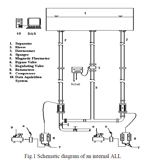
| The schematic diagram of the adiabatic ALL indigenously designed and fabricated for the purpose of the present experiment is shown in Fig 1. It is a vertical, rectangular, open type, internal Air-Lift device. The loop consists of the following components: Two risers, one down comer, lower horizontal section and separator. All components including separator are made of transparent acrylic resin (Polyacrylic mythacralate) that allows direct visualization of the flow pattern throughout the loop. The riser and the down comer are vertical tubes of circular cross section having identical diameters. They are connected at the bottom by a short horizontal section of same diameter. At the top, they are connected to a rectangular, gas-liquid separator, which is open to atmosphere. The details of loop geometrical dimensions are tabulated in Table 1. A gate valve at the bottom most portion of the loop serves for both filling up and draining of the liquid. Air and water are used as the test fluids. A twin cylinder air compressor has been used for the continuous air supply at constant pressure (2 bar at the delivery of the compressor) and at desired flow rate. Compressed air from the compressor passes through the rotameters in sequence before being injected in to the loop. |
| Air flow rate was controlled by the gate valves and fine controlling of air flow rate has been achieved by simultaneous operation of inline and bypass valves. Three calibrated rotameters (range of 6-100 lpm, 6-200 lpm and 0- 10 lpm) of different ranges suitable for the range of operation of the present investigation were used. |
 |
SUBSCRIPTS: |
| A accelerational D downcomer |
| F frictional g gas/air |
| G gravitational L liquid |
| R riser ST storage tank |
| 1 loop 1 2 loop 2 |
| For supply of air into the sytem a sparger is used. Care has been taken in designing the sparger in order to provide uniform mixing of air with water and to avoid any slug formation at the inlet. The sparger is made, attaching a closed annular jacket of diameter 140 mm over the riser tube. The riser tube inside this sparger has been provided with a number of slots of 2 mm width and 270 mm height. An artificial fabric of high porosity has been wrapped over this inner tube. The outer wall of the sparger has also eight holes, four at the top and four at the bottom. Compressed air from the rotameter goes to a distributor having eight ports. Each of these ports is connected with one hole of the sparger through flexible plastic tubing. This ensures uniform supply of air throughout the length of the sparger and entry of air in the riser tube in the form of small diameter bubble through the porous fabric. Smooth rounded riser exit and downcomer entry has been provided to minimize the exit and entry losses. |
Experimental Procedure |
| For experimental study, the loop is filled with water up to a pre-determined height. Air from the compressor is supplied to the loop. Pressure, temperature and flow rate of air is monitored. Keeping the air flow rate constant the loop is allowed to run for certain time. Then signal from measuring instrument installed in the loop are recorded continuously. Visual observation of the flow phenomenon has been made and noted down. Post processing of the signal has been made after they have been recorded. |
| For experimental study, the loop is filled with water up to a pre-determined height. Air from the compressor is supplied to the loop. Pressure, temperature and flow rate of air is monitored. Keeping the air flow rate constant the loop is allowed to run for certain time. Then signal from measuring instrument installed in the loop are recorded continuously. Visual observation of the flow phenomenon has been made and noted down. Post processing of the signal has been made after they have been recorded. |
III. RESULTS AND DISCUSSIONS |
Average Pressure Drop Readings |
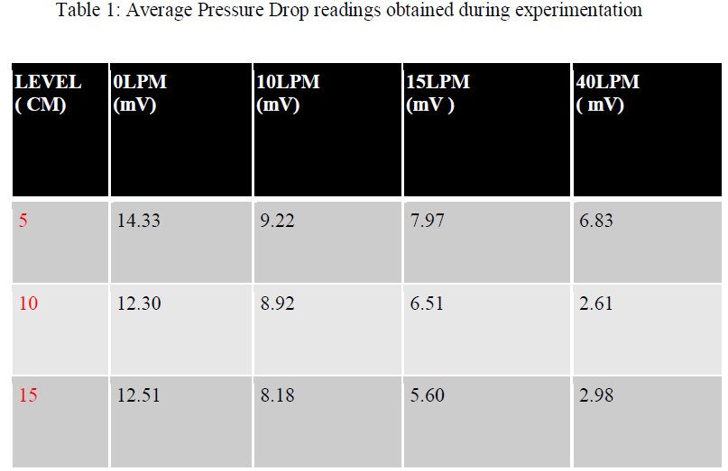
| Average voltage readings obtained while measuring the pressure drop by using the differential pressure transducer, for the various flow regimes in the riser, for the different levels of water in the separator are given below. |
 |
| ïÃâ÷ With the increase of air flow rate, the void fraction through the riser and the circulation rate through the loop increases while the riser pressure drop decreases. |
| ïÃâ÷ With the increase of air flow rate, though, the frictional pressure drop increases, the associated increase in void fraction decreases the gravitational component of the pressure drop. As a result the total pressure drop decreases. |
Analysis |
Variation of Pressure Drop |
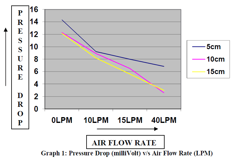
| The variation of Pressure drop, for various air flow rates at different levels of water is shown in the graph below. |
 |
| ïÃâ÷ The overall pressure drop decreases with increase in air flow rate. |
| ïÃâ÷ The level of water does not have any effect in the pressure drop variation. |
IV. CONCLUSION |
Concluding Remarks |
| The experimental investigation about Two-phase flow in an Air Lift Loop has been described in this project. The mixture of water and air is used for the demonstration of Two-phase flows in the present study. |
| ïÃâ÷ The indigenously designed and fabricated experimental facility constitutes an external Air Lift Loop. This is fully instrumented with arrangements for the measurement of air flow tare, circulation rate, local void fraction and pressure drop. All the measurements were done online with the help of a pc based Data Acquisition System. |
| ïÃâ÷ The demonstration of various Flow regimes is done by varying the air flow rate in the Air Lift Loop. |
| ïÃâ÷ With normal liquid level, it was observed that the performance of the Air Lift Loop was much influenced by the air flow rate but relatively insensitive to the variation of liquid level. |
| ïÃâ÷ With the increase of air flow rate, the void fraction through the riser and the circulation rate through the loop increases while the riser pressure drop decreases. |
| ïÃâ÷ With the increase of air flow rate, though, the frictional pressure drop increases, the associated increase in void fraction decreases the gravitational component of the pressure drop. As a result the total pressure drop decreases. |
| ïÃâ÷ The behaviour of Air lift loop reported in this chapter is not only important for understanding the hydrodynamics of Air Lift Loop as such, but also for the other two phase natural circulation loop in general. If in a rectangular two phase natural circulation loop heating is done in the lower horizontal limb, two phase flows will occur in the vertical riser. The characteristics of this flow behavior can be grossly understood from the present study. Moreover, if the vapor phase is to be separated in a heated two phase natural circulation loop, it will need a two phase separator then only it will have vapor free liquid flow through the downcomer. These features are also similar to those present in an Air Lift Loop. Carry-under in the downcomer is a challenging problem in many steam generators. The effect of liquid level on the carry-under can be understood from the present experiment. Finally, one can also have an idea how the low liquid level can induce oscillation in the loop behavior. |
Future Scope of the Project |
| ïÃâ÷ The experimental setup designed has three vertical tubes. Our project is based on two vertical tubes only. |
| ïÃâ÷ For future batches it is recommended to use the third vertical tube for experimentation purpose in the following way: |
| ïÃâ÷ Use of the third tube as the 2nd riser and to analyze the total discharge in the downcomer by the air flow rate in both the risers. |
| ïÃâ÷ Injecting air only in the 2nd riser, to analyze the discharge through the 1st riser and also in the downcomer and to analyze the void fraction, pressure drop in the downcomer as well as the 1st riser. |
| ïÃâ÷ By decreasing the level of water below the separator level and then analyze the void fraction and pressure drop in the down comer. |
| ïÃâ÷ Comparing the experimental data with the theoretical results data and also with results obtained from computational analysis (using CFD software, neural networks). |