ISSN ONLINE(2319-8753)PRINT(2347-6710)
ISSN ONLINE(2319-8753)PRINT(2347-6710)
Akshay Basavaraj1
|
| Related article at Pubmed, Scholar Google |
Visit for more related articles at International Journal of Innovative Research in Science, Engineering and Technology
This paper deals with the 2-D computational analysis of FX 66 S196 airfoil blade which is used in a Vertical Axis Wind Turbine (VAWT) [Ref.1]. The aerodynamic characteristics such as coefficient of lift and coefficient of drag are evaluated from 00 to 3600 using FLUENT 6.3.26. The geometry of the airfoil is developed in GAMBIT 2.4.6. The objective of this paper is to improve the efficiency of the VAWT airfoils at high angles of attack. Experimental results obtained from work done by Avin et al [Ref.4] are compared with for validity of the procedure used in FLUENT
Keywords |
| 2-D computational analysis, Vertical Axis Wind Turbine, Coefficient of lift, coefficient of drag |
| List of symbols used |
| CL – Coefficient of Lift |
| CD – Coefficient of drag |
| α – Angle of attack |
I. INTRODUCTION |
| A vertical axis wind turbine is a device which is used to generate electricity. A VAWT has its axis of rotation in the vertical direction in comparison to traditional wind turbines which have their axis of rotation in the horizontal direction. Some of the problems of VAWTs are its high starting torque and stalling. The high starting torque sometimes can be attributed to structural defects [Ref.2]. There are very few methods in which we can evaluate the performance of the airfoil blade as it completes one rotation. During the rotation, the airfoil undergoes change in its angle of attack from 00 to 3600. This leads to stalling of the airfoil at high values of α which subsequently leads to decrease in efficiency of the VAWT. Due to presence of multiple blades in the VAWT setup, the lift produced by other blades also affects its performance. Therefore, a study of the airfoil characteristics from 00 to 3600 α is necessary in order to improve the performance. |
II. FLOW AROUND A VERTICAL AXIS WIND TURBINE |
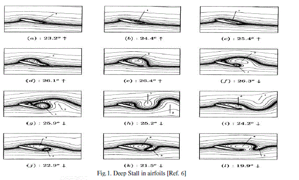
| The increase in the value of α leads to deep stall and dynamic stall of the airfoil blades. The separation can typically start at the trailing edge of the airfoil and shifts forward with increasing angle. If the angle is increased further the separation moves forward to the leading edge. This condition is known as deep stall. Deep stall depends on Reynolds number and leading edge of the airfoil. Dynamic stall is a phenomenon that occurs at airfoils with rapid changing angle of incidence. The resulting effect of this changing angle is a difference, a hysteresis, in the lift, drag and moment characteristics between increasing and decreasing angle of incidence. Dynamic stall is characterized by the shedding and passage of a vortex-like disturbance over the low pressure surface of the lifting body. The main parameter of influence is related to the airfoil motion and the boundary layer separation. |
 |
 |
III. MODELLING AND SIMULATION |
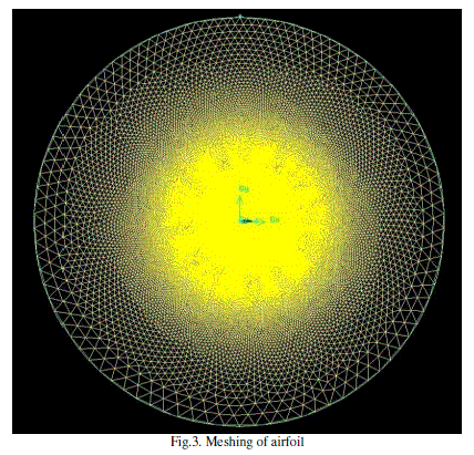
| Aerodynamic characteristics of the airfoil such as lift and drag can be evaluated by wind tunnel testing with the help of pressure ports. Since the procedure is cumbersome and expensive, evaluation of the airfoil characteristics was done using FLUENT. The airfoil chosen for evaluation was FX-66 S-196. The geometry of the airfoil was created in Gambit. A circular far field boundary was created due to its simplicity. Meshing of the airfoil was done as shown below. |
 |
 |
 |
IV. LIFT AND DRAG ESTIMATION |
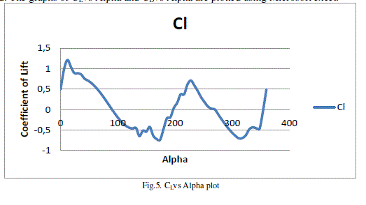
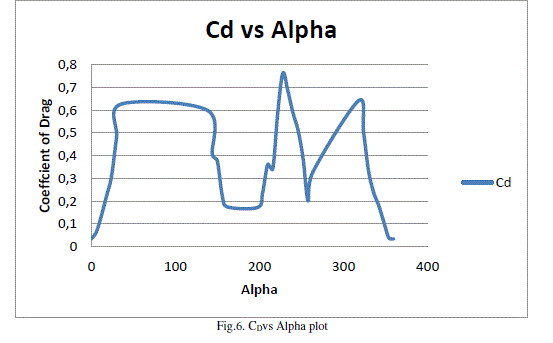
| The coefficient of lift and coefficient of drag at various angles of attack is estimated with the help of a journal file which is developed. The graphs of CLvs Alpha and CDvs Alpha are plotted using Microsoft excel. |
 |
 |
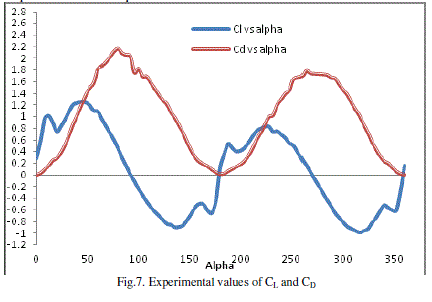 |
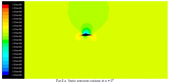
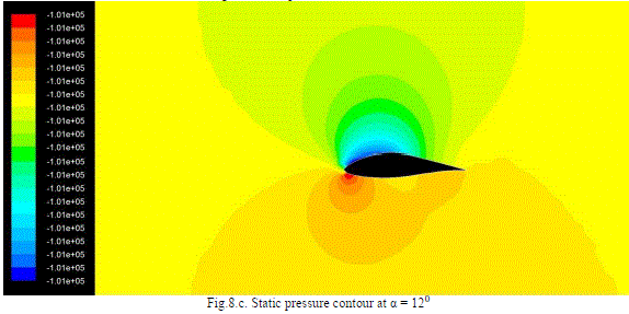
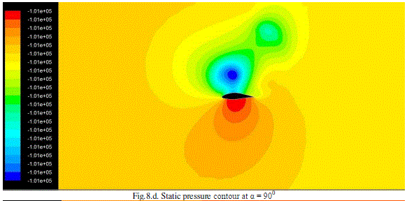
| It can be noted that due to lack of viscosity, the graph shows deviation from its experimental values. The static pressure contours at various α are seen as follows: |
 |
 |
 |
 |
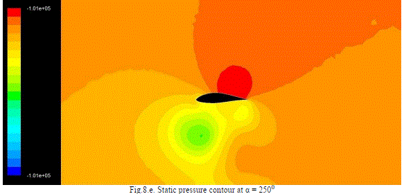 |
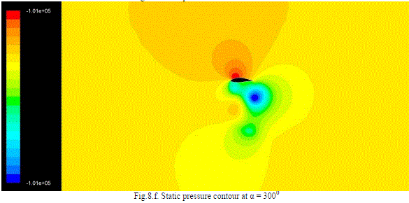 |
| The velocity vectors at different α values are observed as below |
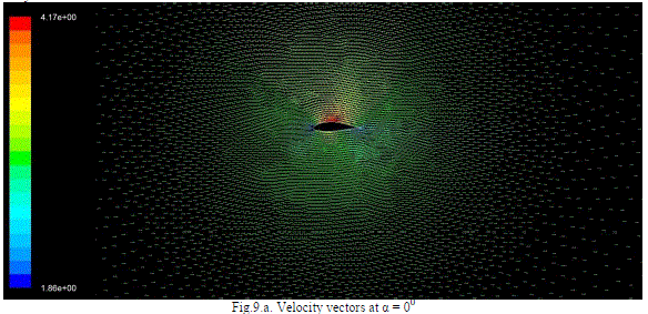 |
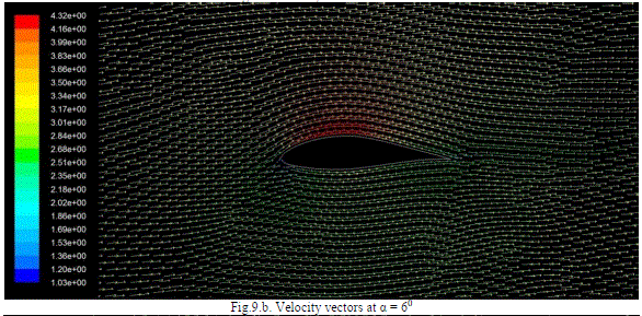 |
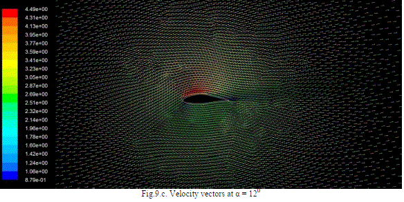 |
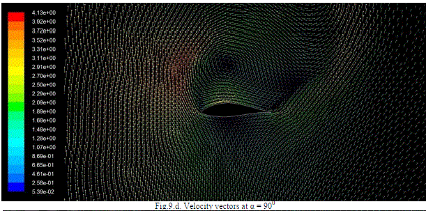 |
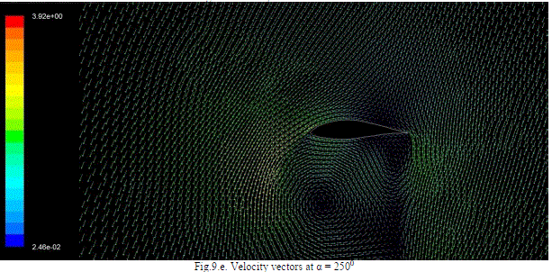 |
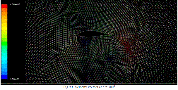 |
V. CONCLUSION |
| Due to unavailability of the airfoil co-ordinates of Avin et al’s work, a proper comparison could not be achieved. Although the inviscid model reaches convergence over a larger range in comparison to its other counterparts, it is not accurate enough to predict the aerodynamic characteristics of the airfoil. The behaviour of the airfoil from α value of 500 to 2000 with regard to the CL variation shows a similar pattern in comparison to its experimental counterpart. The CL variation shows similar pattern from α value of 2500upto 3600. This model can be used to predict to a certain extent the post stall characteristics of the airfoil. Although without the viscous term, it becomes more of a prediction rather than an exact value. This method is useful to maximise the lift during a rotation and determine a better positioning of the blades in a VAWT. Due to lack of accuracy with respect to its behaviour of CD, we can use this only for lift based VAWTs and not drag based VAWTs. |
ACKNOWLEDGEMENT |
| The author would like to thank Dr.BalajeeRamakrishnananda, Assistant professor, Department of aerospace, Amrita School of Engineering, Coimbatore for giving the opportunity to work on this project as part of the curriculum. The author would like to thank whole heartedly Mr.Prabhakaran B. of the 2009-13 B.tech. batch of Aerospace engineering for his invaluable insight with regard to FLUENT and GAMBIT which made the completion of this paper successful. The author would like to thank the Department of Aerospace Engineering of Amrita School of Engineering, Coimbatore as a whole for their unwavering support. |