ISSN ONLINE(2319-8753)PRINT(2347-6710)
ISSN ONLINE(2319-8753)PRINT(2347-6710)
Dr. Trikal Shivshankar1, Patil Chinmay2, Patokar Pradeep3
|
| Related article at Pubmed, Scholar Google |
Visit for more related articles at International Journal of Innovative Research in Science, Engineering and Technology
Advanced manufacturing system is modern computing technology which has made a major impact on engineering design and manufacturing and has assisted in significantly reducing design and production costs, inventory levels and leads times as well as increasing productivity, quality, capitals equipment, utilization and so on. Based on this technology a vast array of equipment has been developed by various industries and research institutes. They have developed the different computer numerical machines which are using the part programming for the manufacturing of the complex shapes and for mass production. In this paper we are present features of computer numerical control machines, controller system of machine like simulator, 2D and 3D part programming, automated modeling of the metal sculpture, reverse engineering with the help of the 3D Scanning and finally fabrication on the vertical milling center. In this venture we developed the metal sculpture through 3D Scanning.
Keywords |
| 3D Scanner, Reverse Engineering, White Line Scanning Machine, Advanced mfg. system. |
INTRODUCTION |
| Automation and mass production are associated with advancement in technology. In the mass production units since the quantity of item required is very high with little or no variety special purpose machine automatic machine or transfer lines have been used. However for job or batch production general purpose machine are being used due to large variety of components and discontinuous demand of products. In the conventional general purpose machine the skilled operator is responsible for many inputs to the machine. The operator, in addition to the physical work of handling the machine, has to do lot of information processing like reading the drawing and checking the dimensions. Although the general purpose machine are very flexible but these flexibility is at the cost of time and productivity. As the degree of complexity of the component increases and the tolerances become closer, the time to produce the component also increases. Since the process is operator dependent, the mistake on the part of operator due to inattention and tiredness, result in production of defective component. To overcome these problems of production, several improvement have been made in the conventional, machine by reducing the manual control elements. The new technology introduced in the market is known as “Advanced Manufacturing System”. In which the numerically controlled machine tool are used for machining operation, processes and controlled with the help of instruction given to the machine tool in coded form is called as “Part Programming”. This technology also uses other methods known as “Reverse Engineering” for the development of the different models by taking the thousands of the co-ordinates from the physically existing model, which is being made by manually by using chisel or other tool. |
COMPUTER NUMERICAL CONTROL |
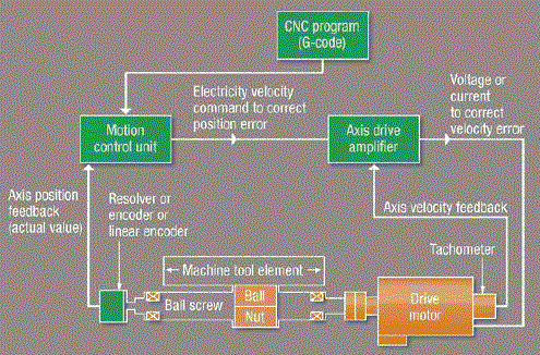
| Computer Numerical Control (CNC), schematically shown in Fig.1, allows a computer to dictate the moves a machine makes to perform cutting function. Originally, all machines were operated manually with the distinct possibility of mistakes. The CNC machine performs these same actions with more precision as well as more speed. The first CNC machines were manufactured in the 1970s to speed up production at large manufacturing plants and were very expensive and difficult to use. The working of CNC based on the signals from the interface control the motors on the CNC machine. The signals determine the way the vice moves. The vice moves in three directions X, Y and Z. (Horizontally, vertically and depth). The signals also control the speed of the cutting tool. |
 |
| A. Features of CNC machine tool |
| Some of feature available in CNC machine are: |
| 1. The part program can be input to the controller unit through keyboard. |
| 2. The part program once enter into the computer memory can be used again and again. |
| 4. The input information can be reduced to great extent with the use of special sub program develop for repetitive machine sequences. |
| 5. The CNC machines have the facility for proving the part program without actually running it on the machine tool. |
| 6. CNC control unit allows compensation for any changes in the dimension of the cutting tool. |
| 7. With the CNC control system, it is possible to obtain information on machine utilization which is useful to the management. |
| B. Advantages of CNC machine |
| 1) Reduce lead time 2) Elimination of operator errors 3) Operator activity 4) Lower labour cost 5) Longer tool life 6) Elimination of special jigs and fixtures 7) Flexibility in changes of component design 8) Reduce inspection 9) Less scrap |
| C. Disadvantages of CNC machine |
| 1) Higher investment cost |
| 2) Higher maintenance cost |
PART PROGRAMMING |
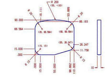
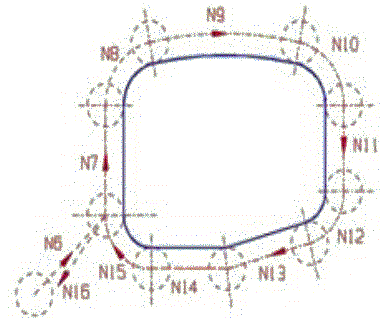
| Part program is an important component of the CNC system. The shape of the manufactured component will depend on how correctly the program has been prepared. Part program is set of instruction which instruct the machine tool about the processing steps to be performed for the manufactured of component. Part programming is the procedure by which the sequence of processing steps and other related data, to be performed on the CNC machine is planned and documented. The part program is then transferred to one of the input medium, which is used to instruct the CNC machine. A sample drawing is shown in fig. 2 and its operation on CNC machine is depicted in Fig. 3. |
| A. Programming example |
 |
| B. Programme |
| N01 G90 |
| N02 G00 X-30 Y-30 Z100 |
| N03 T01 |
| N04 G00 Z5 S1000 M03 |
| N06 G41 G01 X0 Y15 F200 |
| N07 G01 Y66.564 |
| N08 G02 X16.111 Y86.183 I20 J0 |
| N09 G02 X93.889 Y86.183 I38.889 J-196.183 |
| N10 G02 X110 Y66.564 I-3.889 J-19.619 |
| N11 G01 Y26.247 |
| N12 G02 X98.882 Y11.758 I-15 J0 |
| N13 G01 X55 Y0 |
| N14 G01 X15 |
| N15 G02 X0 Y15 I0 J15 |
| N16 G40 X-30 Y-30 |
| N17 G00 Z100 M30 |
 |
COMPUTER AIDED PART PROGRAMMING |
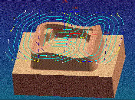
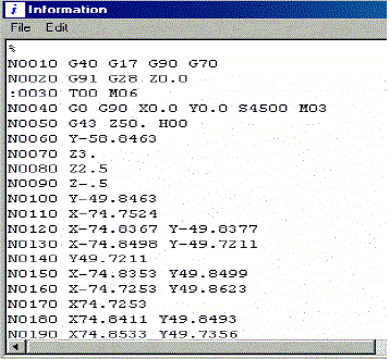
| The method of obtaining part programmes from CAM software by providing CAD model and machining data is Computer Aided Part Programming. Figure 4 and figure 5 show automated tool path generation and automated CNC program generated respectively |
| A. Advantage of using computer-aided part programming |
| 1) Part programming is considerably simplified. 2) The part programmers generated are accurate and efficient. 3) All arithmetic calculations are done by the computer, resulting in saving in the time and elimination of errors. 4) The part programming for different machine can be done by single person, which can then be post processed for specific machines. 5) Such system can deal with many axes for simultaneous movement. 6) If new machine are added, only a post processor may be needed to integrate the new machines with the existing system. |
 |
REVERSE ENGINEERING |
| Reverse Engineering is a process of modifying an existing product after analysing its design and working in detail. It is a process which involves making of 2D drawings, 3D models and assemblies from a model which is already manufactured. Reverse Engineering is generally carried out when there are some design changes to be made or a new part is to be fit into an existing assembly. At Reverse engineering outsourcing, we provide a wide range of reserve engineering services to our customers from around the world. |
| Reverse Engineering is a complex procedure for there are all kinds of freeform shapes and sizes in a physical component. With the advancement in technology, the sizes of components are reducing while their complexities are ever increasing. It is impossible to use traditional Measurement services and manual inspection techniques for Reverse engineering because of the high number of complex surfaces and probable inaccuracy involved. |
THREE DIMENSIONAL (3D) SCANNING |
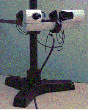
| White light scanning is a 3D scanning process using a non-contact optical scanning device which uses white light source to paper fringes on the part being scanned. The sensor of the scanner which is equipped with one or two cameras take several images of the part (with fringes papered on it) during the measurement and sends these images to a high end PC where an advanced image software calculates point co-ordinates throughout the visible area of the part under scan. Unlike contact scanning, white light scanning picks up the point co-ordinates of the surface being scanned so there is no requirement for probe ball compensation and complexities / errors associated with it. Figure 6 shows the scanning device |
 |
| A. Principle behind the 3d Scanning |
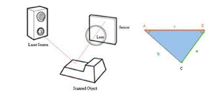
| 1) Laser Triangulation 3D Scanners: Laser triangulation scanners use either a laser line or single laser point to scan across an object. A sensor picks up the laser light that is reflected off the object, and using trigonometric triangulation, the system calculates the distance from the object to the scanner. The distance between the laser source and the sensor is known very precisely, as well as the angle between the laser and the sensor. As the laser light reflects off the scanned object, the system can discern what angle it is returning to the sensor at, and therefore the distance from the laser source to the object’s surface. Figure 7 shows the processs |
 |
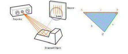
| 2) Structured Light (White or Blue Light) 3D Scanners: Structured light scanners also use trigonometric triangulation, but instead of looking at laser light, these systems paper a series of linear patterns onto an object. Then, by examining the edges of each line in the pattern, they calculate the distance from the scanner to the object’s surface. Essentially, instead of the camera seeing a laser line, it sees the edge of the papered pattern, and calculates the distance similarly. The white Light scanning system, as shown in figure 8, fringe patterns on the component and the camera simultaneously capture images, then advanced software algorithms triangulate and calculate 3d-coordinates of numerous points spaced all over the surface of the part. The area of the part that is within the frame (illuminated zone with fringes) gets scan during a single measurement. For scanning complete part several such measurements are carried out and merged together with the help of markers fixed on the part. |
 |
| 3) Data obtained from 3D Scanning: The data acquired from 3D Scanning, can be used during the product design phase to input physical models into CAD/CAM world, during the manufacturing phase to generate tool paths for machining and also during the quality assurance phase to verify dimensional accuracy of the final product. |
| B. Advantages of 3D scanning |
| 1) The primary advantage of 3D Scanning is that the process is non-contact, fast and results in coordinate locations that lie directly on the surface of the scanned object. This allows fragile parts to be measured and makes the scanned coordinate locations especially useful to CAD/CAM systems where surfacing through true surface coordinates is desirable. |
| 2) The laser and white light also permits scanning of highly detailed objects where mechanical touch probes may be too large to accomplish the task. Also, while many touch probe systems attempt to compute true surface coordinates by sensing probe deflection, there are certain geometries where probe deflection can be "fooled". 3) As compared to other techniques such as CMM, it is more accurate and precise method. For 3D White Light Scanning, accuracy lies below 40 microns. |
| 4) Once true surface coordinates have been collected for an object, a single set of data can be used to generate roughing and finishing tool paths for machining, feed CAD/CAM and analysis software, drive rapid prototyping equipment, and allow "electronic archiving" of physical objects. |
| C. Limitations of 3D Scanning |
| 1) This method is not suited for the area of the object where laser or white light cannot be reached or reflected back. 2) The initial cost of machine is high. 3) For its better operation, it requires a highly skilled operator. |
METHODOLOGY OF USING 3D SCANNER FOR MANUFACTURING |
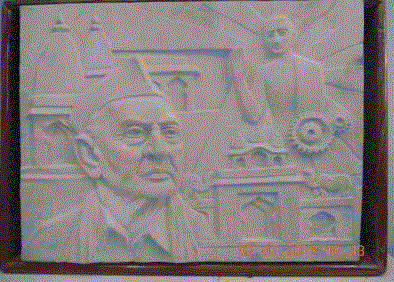
| 1) Making of model: - Initially we require having a model (Figure 9) from any suitable material which contains the details of the part. The finishing of metal sculpture will depend upon the finishing of model. |
 |
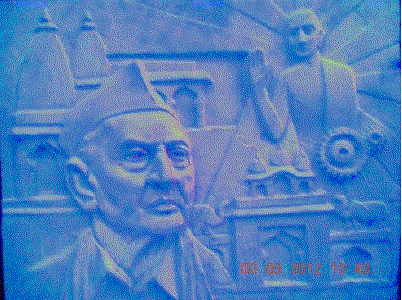
| 2) 3D Scanning & 3D model generation:- After model, with 3D Scanner the details are captured in the form of point cloud. Further from the point cloud a cad model (Figure 10) is generated by using the software available with scanner. |
 |
| 3) Part program generation by using CAM software: - The 3D model thus obtained from the 3D scanner is loaded into CAM software for generation of the part program. 4) Modification of part program according to machine parameter: - The extracted part program was obtained can be modified as per the machining requirement and machine constraints. 5) Actual running of program: - After setting the workpiece and the machine parameter actual machining is to be done by running the program tool cuts the workpiece as the part program goes on executing. The cutting operation has three steps: - 1) roughing 2) semi finishing 3) finishing. Figure 11 and figure 12 depict the operations 6) The program took around eight hours to complete and convert the raw material into required output. |
 |
CONCLUSION |
| The metal sculpture was designed and successfully fabricated. By using the advanced technology we reduced human efforts for fabricating which was higher in the case of casting method. We used the advanced technology for developing the complex geometry by reverse engineering. We were having various types of modern CNC Machines in the workshop. So we used those available machines and also learned various advanced manufacturing systems which are 3D Scanning specially White Light Scanning, CAD/CAM Software like Unigraphics, CNC Simulators and Various Machine Tools with reverse engineering aspect. |