Keywords
|
| Multilevel Inverter, Photovoltaic (PV) system, Pulse Width-Modulation (PWM), Total Harmonic Distortion (THD). |
INTRODUCTION
|
| In recent years, solar-energy power-generation systems have increased significantly their capacity. Nowadays Photovoltaic growth is gradually increased in India.Multilevel inverters are mainly utilized to synthesis a desired single or three phase voltage waveform. The desired multi-staircase output voltage is obtained by combining several dc voltage sources. Solar cells, fuel cells, batteries and ultra-capacitors are the most common independent sources used. One important application of multilevel converters is focused on medium- and high-power conversion. Nowadays, there exist three commercial topologies of multilevel voltage-source inverters: Neutral Point Clamped (NPC), Cascaded H-Bridge (CHB), and Flying Capacitors (FCs). Among these inverter topologies, cascaded H-bridge inverter reaches the elevated output voltage & power levels and the higher reliability due to its modular topology. |
| Diode-clamped multilevel inverters are complicates the design and raises reliability and cost concern.They are also utilized in oil mills, metal works places, power generations, mining process and chemical industry. They have been reported to be used in a back-to-back configuration for regenerative applications. Flying capacitor multilevel converters have been used in high-bandwidth high-switching frequency applications [5]. Finally, cascaded H-bridge multilevel inverter has been used for both high power and medium power application. Furthermore, one of the growing applications of cascade H-bridge multilevel inverter is used in Uninterruptible Power Supplies (UPS)and PV [3].For increasing voltage levels the number of switches also will increase in number. Hence the voltage stresses and switching losses will increase and the circuit was becomes complex. By using the proposed topology number of switches will reduce significantly and hence the efficiency will improve. |
| In high power applications, the harmonic content of the output waveforms has to be reduced as much as possible in order to avoid distortion in the load and to reach the maximum energy efficiency. The challenge associated with techniques is to obtain the analytical solutions of the non-linear transcendental equations that contain trigonometric terms which naturally exhibit multiple sets of solutions. Generally the lower order harmonics are causing more effects when compared to the higher order harmonics. It is very big challenges for all researchers to eliminate the lower order harmonics using PWM techniques [4]-[8]. |
| Traditional three level inverters are investigated with the harmonic analysis and cascaded H-bridge seven-level inverter is modelled and harmonic analysis is carried out. Finally the proposed topology is presented with the implementation of PWM. The THD values for the Conventional and Proposed inverters were analysed [4]. |
H-BRIDGE MULTILEVEL INVERTER
|
| The traditional two or three levels inverter does not completely eliminate the unwanted harmonics in the output waveform. Therefore, using the multilevel inverter as an alternative to traditional PWM inverters is investigated [2],[7]. |
| In this topology the number of phase voltage levels atthe converter terminals is 2N+1, where N is the number of cells or dc linkvoltages. In this topology, each cell is separate by individual dc link capacitor and the cellsacross the capacitor might have different voltage drops. Therefore it requires one dc voltage source for each power circuit. The number of dc link capacitors is proportional tothe number of phase voltage levels.Each H-bridge cell might have positive, negative or zero voltage. Final output voltage is the sum of all H-bridge cell voltages and is symmetric with respect to neutral point, so the number of voltage levels is odd. |
| Cascaded H-bridge multilevel inverters typically use IGBT switches [2]. Theseswitches have low block voltage and high switching frequency. |
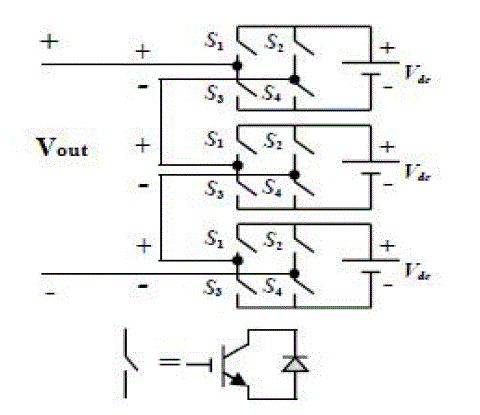
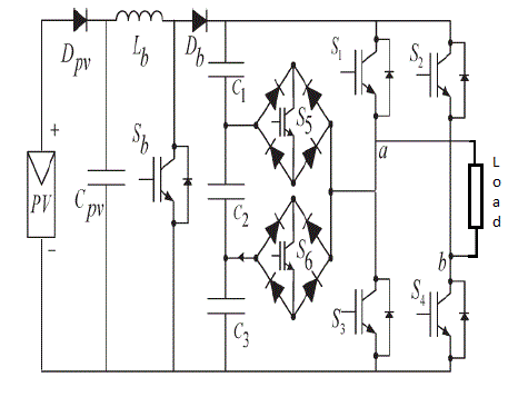
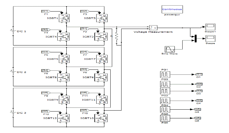
| Consider the seven-level inverter:It requires 12 IGBT switches and three dc sources. The power circuit of inverter is shown in the Fig.1. A cascaded H-bridges multilevel inverter is simply a series connection of multiple H-bridge inverters. Every H-bridge inverter has the same configuration as a typical single-phase full-bridge inverter. |
| The cascaded H-bridges multilevel inverter introduces the idea of using Separate DC Sources (SDCSs) to produce an AC voltage waveform. AllH-bridge inverter is connected to its own DC source Vdc[7]. AC voltage waveform is obtained by cascading the each H-bridge inverter. |
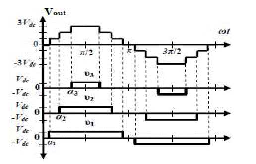
| Each H-bridge inverter can create three different voltages: +Vdc, 0 and -Vdc. |
| It is also possible to be modularized circuit layout and packaging because each level has the same structure, and does not have extra clamping diodes or voltage matching capacitors. The number of switches is reduced using the modified H-bridge inverter topology. |
PROPOSED NOVEL TOPOLOGY
|
| The main objective is to produce the quality output voltage of the multilevel inverter with reduced number of switches. An important issue in multilevel inverter design is that the voltage waveform is near sinusoidal and the lower order harmonics are eliminated [3],[8]. |
| A key concern in the fundamental switching scheme is to determine the switching angles in order to produce the fundamental voltage without generating specific lower order harmonics. |
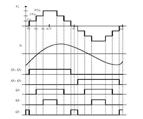
| There are seven modes of switching operation for the 7-level multilevel inverter. These modes are shown as in below table-I. |
| The proposed topology has the advantage of the reduced number of power switching devices, but on the outlay of the high rating of the main six switches. Hence, it is recommended for medium power applications. |
| From the Fig. 4 switching pattern for the various switches are explained. In this paper fundamental frequency switching scheme is employed which reduces the switching losses. Because switching frequency is less in this method when compared to the other devices. Switching losses are directly proportional to the switching frequency. |
PWM MODULATION
|
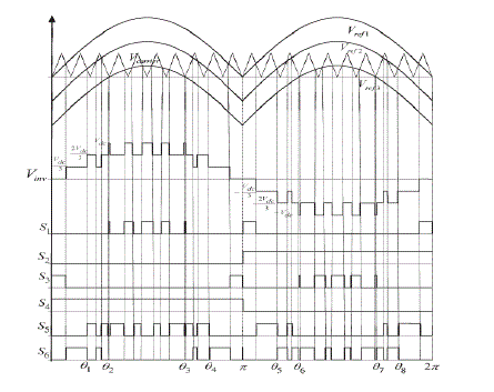
| A novel PWM modulation technique was introduced togenerate the PWM switching signals. Three reference signals(Vref1, Vref2, and Vref3) were compared with a carrier signal(Vcarrier), so it called Carrier based Pulse Width Modulation (CPWM). The reference signals had the same frequency andamplitude and were in phase with an offset value that wasequivalent to the amplitude of the carrier signal. The referencesignals were each matched with the carrier signal. If Vref1 had overdone the peak amplitude of Vcarrier, Vref2 was comparedby Vcarrier until it had exceeded the peak amplitudeof Vcarrier. Formerly,Vref3 would take charge and wouldbe compared with Vcarrier until it reach zero. |
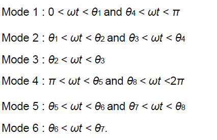
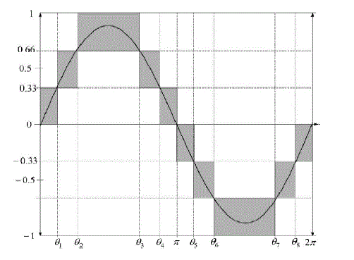
| Once Vref3 had reaches zero, Vref2 would be compared until it reached zero. Then,Vref1 would be compared with Vcarrier. Fig. 5 shows the resulting switching pattern. Controls S1, S3, S5,and S6 would be switching at the rate of the carrier signalfrequency, however S2 and S4 would function at a frequency thatwas equivalent to the fundamental frequency [6],[1].For one cycle of the fundamental frequency, the proposedinverter runs over six modes. Fig. 6 shows the per unitoutput-voltage signal for one cycle. |
| The six pulses of modes aredescribed as follows: |
 (1) (1) |
| The phase angle depends on modulation index Me. Theoretically, for a single reference signal and a single carrier signal, the modulation index is defined as |
 (2) (2) |
| While for a single-reference signal and a three carrier signal, the modulation index is defined as |
 (3) (3) |
| Since the proposed seven-level inverter utilizes PWM switching of three carrier signals, the modulation index is well-defined as |
 (4) (4) |
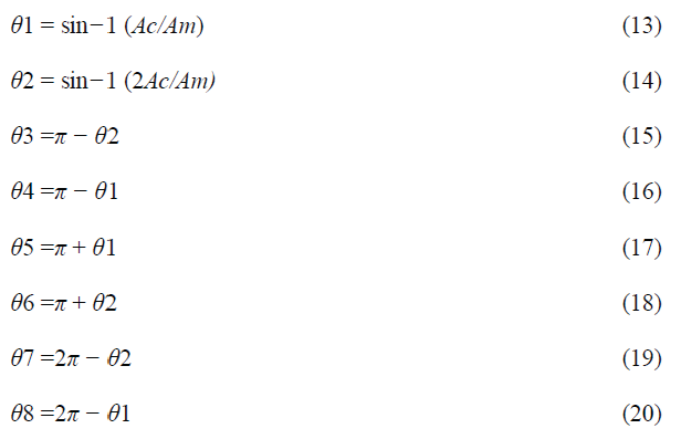
| Where Ac is the peak-to-peak value of the carrier signal and Am is the peak value of the voltage reference signal Vref . When the modulation index is lesser than 0.33, the phase angle displacement is |
 (5) (5) |
 (6) (6) |
| On the other hand, when the modulation index is higher than0.33 and lesser than 0.66, the phase angle displacement isdetermined by |
 (7) (7) |
 (8) (8) |
 (9) (9) |
 (10) (10) |
 (11) (11) |
 (12) (12) |
| If the modulation index is other than 0.66, the phase angledisplacement is determined by |
 |
| For Me that is equal to, or less than 0.33, simply the lowerreference wave (Vref3) is compared with the triangular carriersignal. The inverter’s performance is similar to that of aconventionalfull-bridge three-level PWM inverter. However,if Me is more than 0.33 and less than 0.66, individual Vref2 andVref3 reference signals are compared with the triangular carrierwave. Themodulation index is fixed to be more than 0.66 for seven-level of output voltage to be created. Three reference signals haveto be matched with the triangular carrier signal to produceswitching signals for the switches. |
SIMULATION
|
| The MATLAB simulation circuit was developed for the conventional seven-level and proposed inverter with PWM implementation. |
| A. Simulation of Conventional Seven Level Inverter |
| This circuit consists of 12 IGBT switches with 3 equal dc sources. The gate pulses are generated by using the pulse generator. |
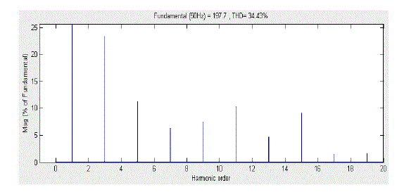
| From the harmonic analysis of seven level output voltage of the 12 switch H-bridge inverter, the THD value is obtained as 34.43%. |
| B.Simulationof the Proposed PV model |
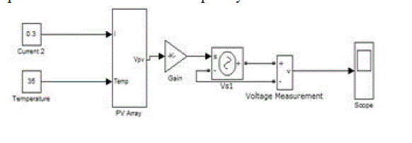
| The simulation model of a PV cell is shown Fig. 9. It consists of an ideal current source and temperature source are connected to PV array block.The current sources represent the current generated by photons and its output is constant under constant temperature and constant incident radiation of light. |
| There are two key parameters temperature and current source frequently used to characterize a PV cell. |
| C.Simulation of the Proposed Boost Converter |
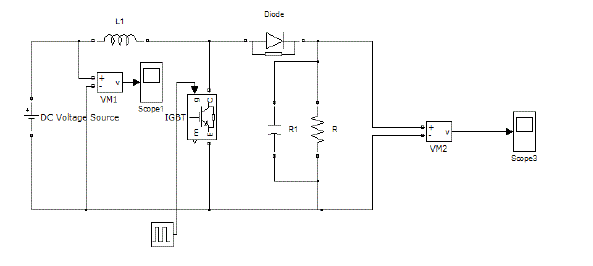
| The simulation model of a boost converter is shown Fig. 10. Its output voltage is higher than the input voltage. Whenever the IGBT is turned on energy is stored on the boost inductor. When the IGBT is turned off the voltage across the inductor reverses and adds to the input voltage to charge the output capacitor. |
| During the time switch is closed, the inductor current increases linearly. When the switch is open, the inductor current decreases linearly and reaches to its minimum level. PV output is connected to the boost converter. |
| D.Simulation of the Proposed Inverter Topology |
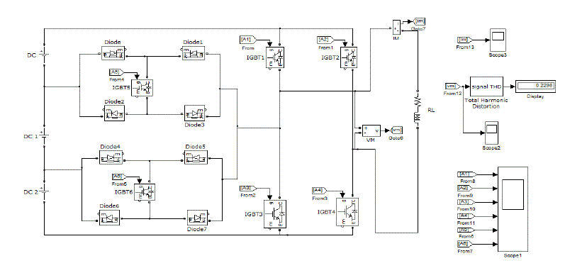
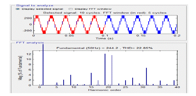
| The Simulink model diagram for the proposed circuit is shown in Fig. 11. It recounts the development of a novel modified H-bridge single-phase multilevel inverter that has two diode embedded bidirectional switches and a novel Carrier based pulse width modulated (CPWM) technique. The topology was applied to a commercial load connected photovoltaic system. It has only six switches and also to reduce THD in the inverter output.Its THD value is obtained as 22.85%, which is the best among convention method inverter. This proposed harmonic shows that improvement of quality in inverter output voltage. |
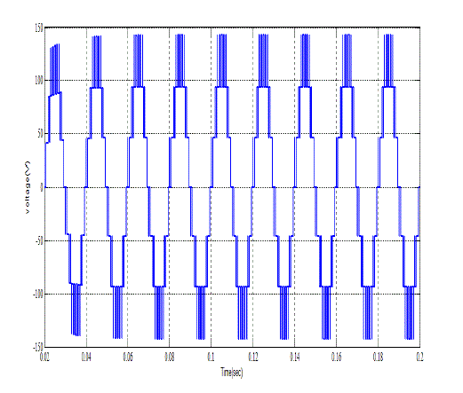
| From the Fig.12 it is clear that seven-level or three stepped waveform is obtained. Then harmonic analysis is carried out with the resistive load. |
| The Simulink model diagram of the proposed inverter THD analysis is shown in Fig. 13. Its THD value is obtained as 22.85%, which is the best among convention method inverter. This proposed harmonic shows that improvement of quality in inverter output voltage. |
CONCLUSION
|
| This paper proposed a single-phase multilevel cascaded H-bridge inverterfor PV Sources. It utilizes three reference signals and a carrier signal to generate CPWM switching. The circuit topology and operational principle of the proposed inverter were analyzed in detail. Its performance satisfies the demand of flexible andaccurate electric power generation. Due to its modularity,the proposed system can be improved by increasing the number of levels was reduced its THD.Simulation results indicate that the THD of the seven-level inverter is much lesser than that of the conventional seven-level inverter.Furthermore based on these results, it is expected that MLIs for PV systems will become an effectively implemented for commercial application shortly. |
| |
Tables at a glance
|
 |
| Table 1 |
|
| |
Figures at a glance
|
 |
 |
 |
 |
 |
| Figure 1 |
Figure 2 |
Figure 3 |
Figure 4 |
Figure 5 |
| |
 |
 |
 |
 |
 |
| Figure 6 |
Figure 7 |
Figure 8 |
Figure 9 |
Figure 10 |
| |
 |
 |
 |
| Figure 11 |
Figure 12 |
Figure 13 |
|
| |
References
|
- Nandor Bodo, Emil Levi and Martin Jones “Investigation of Carrier-Based PWM Techniques for a Five-Phase Open-End Winding DriveTopology” IEEE Trans. Ind. Electron., vol. 60, no.5, pp.2054-2065, Mar 2013.
- NasrudinAbd. Rahim, Mohamad Fathi Mohamad Elias and Wooi Ping Hew “Transistor-Clamped H-Bridge Based Cascaded MultilevelInverter With New Method of Capacitor Voltage Balancing” IEEE Trans. Ind. Electron., vol. 60, no. 8, pp. 2934-2956, Aug 2013.
- Abdalla, J. Corda, and L. Zhang ”Multilevel DC-Link Inverter and Control Algorithm to Overcome the PV Partial Shading” IEEE Trans. PowerElectron., vol. 28, no. 1, pp. 14-18, Jan 2013.
- Dragutin J. Kostic, Zoran Z. Avramovic and Ninoslav T. Ciric “A New Approach to Theoretical Analysis of Harmonic Content of PWMWaveforms of Single- and Multiple-Frequency Modulators” IEEE Trans. Power Electron., vol. 28, no. 10, pp.4557-4567, Oct 2013.
- Ke Ma and FredeBlaabjerg “Modulation Methods for Neutral-Point-Clamped Wind Power Converter Achieving Loss and ThermalRedistribution Under Low-Voltage Ride-Through” IEEE Trans. Ind. Electron., vol. 61, no. 2,pp.835-845, Feb 2014.
- Salvador Alepuz, Sergio Busquets-Monge, JosepBordonau, Juan A. Martínez-Velasco, César A. Silva, Jorge Pontt and José Rodríguez“Control Strategies Based on Symmetrical Components for Grid-Connected Converters Under Voltage Dips” IEEE Trans. Ind. Electron., vol.56, no. 6, pp.2162-2173, Jun 2009.
- Elena Villanueva, Pablo Correa, José Rodríguez and Mario Pacas “Control of a Single-Phase Cascaded H-Bridge Multilevel Inverter for Grid-Connected Photovoltaic Systems” IEEE Trans. Ind. Electron., vol. 56, no. 11,pp.4399-4406, Nov 2009.
- Chih-Chiang Hua, Chun-Wei Wu and Chih-Wei Chuang “A Digital Predictive Current Control With Improved Sampled Inductor Current forCascaded Inverters” IEEE Trans. Ind. Electron., vol. 56, no. 5,pp.1718-1726, May 2009.
- Carlo Cecati, FabrizioCiancetta and PierluigiSiano “A Multilevel Inverter for Photovoltaic Systems With Fuzzy Logic Control” IEEE Trans.Ind. Electron., vol. 57, no. 12,pp.4115-4125, Dec 2010.
- Jeyraj Selvaraj and Nasrudin A. Rahim “Multilevel Inverter For Grid-Connected PV System Employing Digital PI Controller” IEEE Trans. Ind.Electron., vol. 56, no. 1, Jan 2009.
|