Keywords
|
| H.264, COMPOUND IMAGE, JPEG, DCT, INTRA PREDICTION. |
INTRODUCTION
|
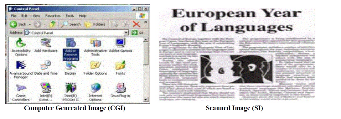
| Digital image compression is the method of image data rate reduction to save storage space and reduce transmission rate requirements. However, the fast development of the Internet and widespread rich media applications produce not only text, natural and graphical images but also images that combine these three together. These images are termed as „Compound images? and examples include computer generated images, text images, scanned images, document images, etc. The examples of compound images are shown in Fig(1). |
| In this paper, the three different image compression algorithms are discussed and compared for both natural and compound images. The first algorithm is Discrete Cosine Transform. The discrete cosine transform is a fast transform. It is a widely used and robust method for image compression. It has excellent compaction for highly correlated data. DCT has fixed basis images DCT gives good compromise between information packing ability and computational complexity [1]. The second algorithm is JPEG (Joint Picture Expert Group) algorithm. JPEG uses a lossy form of compression based on the discrete cosine transform (DCT). |
| The compression is performed by a series of operations: transform, quantization, zigzag scanning, differential pulse code modulation (DPCM), and entropy coding. Decompression is accomplished by performing inverse steps in an inverse order. We assume the data is only available in compressed format. It is the best compression for natural photos compare to other techniques [2]. The last algorithm is H.264. It is very useful for normal and compound images. It has better PSNR values to compare DCT and JPEG. It is block based technique, in this the compound image/normal image is divided into 16*16 macro blocks using segmentation. This is to perform intra prediction before transform as H.264 intra coding. The new aspect in H.264 is the use of a 4*4 transforms block size, whereas previous image coding standards used the 8*8 DCT. This smaller block size leads to a significant reduction in ringing artifacts [3]. In this compression is performed a series operations: intra prediction, transform, quantization, zigzag scanning and entropy encoding. Reconstruction is accomplished by performing inverse steps in an inverse order [4]. |
COMPRESSION TECHNIQUES
|
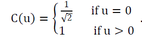
| A) DISCRETE COSINE TRANSFORM: - The discrete cosine transform (DCT) has been applied extensively to the area of image compression. It is developed by Ahmed, Natarajan, and Rao [1974], the DCT is a close relative of the discrete Fourier transform (DFT). Its application to image compression was pioneered by Chen and Pratt [1984]. By using DCT to reduce the inter pixel redundancy. In the compression process the input image is divided into 8*8 blocks of pixels and then each block is applied to the forward 2-D discrete cosine transform then we will get the transformed image. When desired, the image is reconstructed through decompression. A process that uses the inverse discrete cosine transform (IDCT). Image is a 2-Dimensional array because here we use the 2-D DCT. The 2-D Discrete Cosine Transform is just a one dimensional DCT applied twice, once in the X-direction, and again in the Y-direction. The DCT equation computes the (i,j) entry of the DCT of an image. The equation 2-D DCT is shown below. |
 (1) (1) |
 (2) (2) |
| P(x,y) is the element of the image represented by the matrix P,N is the size of the block that the DCT is done on. The equation calculates one entry ((i,j)th) of the transformed image from the pixel values of the original image matrix. For the standard 8 × 8 block that DCT compression uses, equals 8 and x and y range from 0 to 7. Therefore D(i,j) would be as in Equation. |
 (3) (3) |
| The original samples from image can be recomputed again from DCT coefficients by applying the Inverse Discrete Cosine Transform (IDCT). The mathematical formulae of IDCT for the block size of 8 X 8 is given by |
 (4) (4) |
| THE DCT MATRIX: To get the matrix form of Equation (1), we will use the following equation, |
 (5) (5) |
| When doing the inverse DCT the orthogonality of T is important, as the inverse of T is T' which is easy to calculate. In the input image, the 8*8 block was chosen from the very upper- left-hand corner of an image i.e M. Where ready to perform the DCT, which is accomplished by matrix multiplication. |
 (6) (6) |
| In the above equation D is the transformed image matrix. A portion of D is selected on D? which has the coefficients from 0 to 3 in both dimensions. D? is the compressed format of D with 1:4 compression. |
 (7) (7) |
| Where D11 is reformulated image matrix at the receiver as shown in eqn (7). In D' ' O indicates 4*4 zeros. Then it will be reconstructed by using inverse discrete cosine transform. The reconstructed image(R) as given in equation 8. |
 (8) (8) |
| B) JPEG COMPRESSION ALGORITHM: - JPEG uses a lossy form of compression based on the discrete cosine transform (DCT). There are several variations of JPEG, but only the 'baseline' method is discussed. |
| As shown in the Fig 1.1, the image is first partitioned into non-overlapping8 × 8 blocks. A Forward Discrete Cosine Transform (FDCT) is applied to each block to convert the spatial domain gray levels of pixels into coefficients in frequency domain. After the computation of DCT coefficients, they are normalized with different scales according to a quantization table provided by the JPEG standard conducted by psycho visual evidence. The quantized coefficients are rearranged in a zigzag scan order for further compressed by an efficient lossless coding algorithm such as run-length coding, arithmetic coding, Huffman coding. The decoding process is simply the inverse process of encoding as shown in the Fig 1.2. |
| The block diagram of a JPEG decoder is shown in above figure. Decompression is accomplished by applying the inverse of each of the preceding steps in opposite order. Thus, the decoding process starts with entropy decoding and proceeds to convert the run lengths to a sequence of zeros and coefficients. Coefficients are dequantised and Inverse Discrete Cosine Transform (IDCT) is performed to retrieve the decompressed image. |
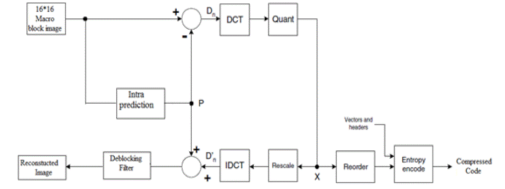
| C) PROPOSED ALGORITHAM:-The proposed algorithm is named as h.264 algorithm. It is very useful for natural and compound images. It has better PSNR values and better compression efficiency comparative both algorithms. The block diagram of h.264 encoder and decoder as show Fig 1.3. |
| There are two main data flow paths in the above diagram, left to right (encoding) and right to left (reconstruction). The encoding flow is as follows: |
| 1) The original image is divided into 16*16 macro blocks by using block based segmentation and then applies intra prediction. |
| 2) The intra prediction in the H.264 standard effectively reduces the spatial correlation among 16 × 16 and 4 × 4 blocks, where the current block is predicted by adjacent pixels in the upper and left blocks and generated P. |
| 3) P is subtracted from the original macro block to produce a residual or difference macro block D. |
| 4) D is transformed using the DCT. Typically, D is split into 8 × 8 or 4 × 4 sub-blocks and each sub-block is transformed separately. |
| 5) Each sub-block is quantised (X). |
| 6) The DCT coefficients of each sub-block are reordered and run-level coded. Finally, the coefficients, vectors and associated header information for each macro block are entropy encoded (Huffman encoding) to produce the compressed bit stream. |
| The reconstruction data flow is as follows: |
| 1) Compressed bit stream is entropy decoded (Huffman decoded) to extract coefficients, motion vector and header for each macro block |
| 2) Run-length coding and reordering are reversed to produce a quantised, transformed macro block X. |
| 3) X is rescaled and inverse transformed to produce a decoded residual D. |
| 4) P is added to D_ to produce a reconstructed macro block. The reconstructed macro blocks are saved . |
| 5) The reconstructed macro blocks are passed through the deblocking filter then we get recovery image. |
| The input image (normal image type) used to carry out the experiments is shown in fig 1.4 and the reconstructed image is shown in fig 1.5. The mean square error and peak signal to noise ratio values for this image and of images are given in table 2.1. |
CHARACTERISTICS OF THE COMPRESSION ALGORITHM
|
| Image quality describes the fidelity with which an image compression scheme recreates the source image data. There are four main characteristics to judge image compression algorithms. |
| i) Compression ratio: The compression ratio is equal to the size of the original image divided by the size of the compressed image. This ratio gives how much compression is achieved for a particular image. The compression ratio achieved usually indicates the picture quality. Generally, the higher the compression ratio, the poorer the quality of the resulting image. The tradeoffs between compression ratio and picture quality is an important one to consider when compressing images. Some compression schemes produce compression ratios that are highly dependent on the image content. This aspect of compression is called data dependency. |
| ii) Compression time: Compression time and decompression time are defined as the amount of time required to compress and decompress a picture, respectively. Their value depends on the following considerations: |
| • The complexity of the compression algorithm. |
| • The efficiency of the software or hardware implementation of the algorithm. |
| • The speed of the utilized processor or auxiliary hardware. |
| iii) Mean square error: Mean square error measures the square error between the original and the compressed image. The formula for mean square error is given as |
 |
| Where M X N is the size of the image, f'(i,j) and f(i,j) are the matrix element of the decompressed and the original image at (i,j) pixel. |
| iv) Peak signal to noise ratio: The Peak signal to noise ratio calculated between the input original image and the reconstructed image is known as PSNR.PSNR is most commonly used to measure the quality of reconstruction of lossy compression codec?s (e.g., for image compression).It is usually expressed in terms of the logarithmic decibel scale .The formula for PSNR is given as |
 |
| Here, MAXi is maximum possible pixel value of an image. When the pixels are represented using 8 bit per sample, this is 28-1=255.More generally, when samples are represented using linear PCM with B bits per sample, then MAXi=2B-1. |
COMPARISION RESULTS
|
| Different lossy compression methods using DCT, JPEG and H.264 algorithms are presented for different types of images (normal, compound, word, power point). The mean square error and peak signal to noise ratios values are compared in the table1.1. It is observed that the mean square error & peak signal to noise ratio values for H.264 algorithm are better is compared to the other two methods. |
CONCLUSION
|
| In these paper four different types of images are taken, like normal, compound, word, power point images for compression and decompression. All these images are compressed and decompressed by using three different methods. It is observed that the H.264 method has provides better mean square error and peak signal to noise ratio values for all types of images in comparing with other two methods. Hence H.264 method is best in comparison with DCT and JPEG in terms of mean square error and peak signal to noise ratio. |
| |
Tables at a glance
|
 |
| Table 1 |
|
| |
Figures at a glance
|
 |
 |
 |
| Figure 1 |
Figure 1a |
Figure 1b |
| |
 |
 |
 |
| Figure 1c |
Figure 1d |
Figure 1e |
|
| |
References
|
- Rafael C.Gonzalez and R.E.Woods, Digital Image Processing, 5th edition, Addison Wesley,India,2000.
- Recommendation T.81, International Telecommunication Union (ITU) Std., Sept. 1992, joint Photographic Expert Group (JPEG).
- ISO/IEC 14496-10 and ITU-T Rec. H.264, Advanced Video Coding, 2003.
- R.Aparna, D.Maheswari, Dr.V.Radha, Performance Evaluation of H.264/AVC Intra Compound Image Compression System, 2010 InternationalJournal of Computer Applications.
- Wenpeng Ding, Yan Lu, Feng Wu and Shipeng Li (2007), Rate-Distortion Optimized Colour Quantization For Compound Image Compression,SPIE proceeding, Vol. 6508, pp 1-9.
- ISO/IEC JTC1/SC29 WG1, JPEG 2000 Committee, JPEG 2000 Verification Model (Technical Description), April 22, 1999.
- Ding, W., Lu, Y. and Wu,F. (2007) Enable Efficient Compound Image Compression in H.264/AVC Intra Coding, IEEE International Conferenceon Image Processing, Vol. 2, Pp. II - 337 - II – 340.
- Zaghetto, A. and de Queiroz, (2007) Using H.264/AVC-Intra for Segmentation- Driven Compound Document Coding, IEEE ICIP 2007, Pp. II-333 – II-336.
- B. Wu, C. Chiu and Y. Chen “Algorithms for compressing compound document images with large text/background overlap”, IEE Proc. Vis.Image signal Process., vol. 151 no. 6, pp. 453-459 , Dec. 2004.
|