Keywords
|
| Transfer function, PID controller, tuning of PID controller, error criteria- IAE, ISE, ITAE, temperature control. |
INTRODUCTION
|
| In general, PID controller is a generic control loop feedback mechanism which is used to calculate the error values. It calculates the error values by means of measuring the difference between process variable and set point [1]. A PID controller is a simple three-term controller where Proportional, Integral and Derivative. Proportional depends upon the present error, and its offset is more. Integral depends on past error, where it can overcome the offset but it overshoots value is more. Derivative depends upon the future error but it can overcome both offset and overshoot, but it cannot be used separately [3]. The output of controller is given by |
 (1) (1) |
| Kp = Proportional gain |
| Ki = Integral gain(Kp /τi) |
| Kd = Derivative gain (Kp *τd) |
| C(t) = Controlling signal. |
| e(t) = error signal with respect to time |
| Matlab based real time control is realize in this study, to control the temperature of the experimentation set is more realistic [12]. This software could be used for training continuous control modes such as Proportional control, Proportional Integral control and PID control, the paramount of all control modes. Arithmetical equations used to describe these modes have been solved using MATLAB program. Separate algorithms and MATLAB program have been developed for all these control modes. 2D plots enclose been generated in support of visualization of controller output. |
TEMPERATURE MODEL KIT DETAILS
|
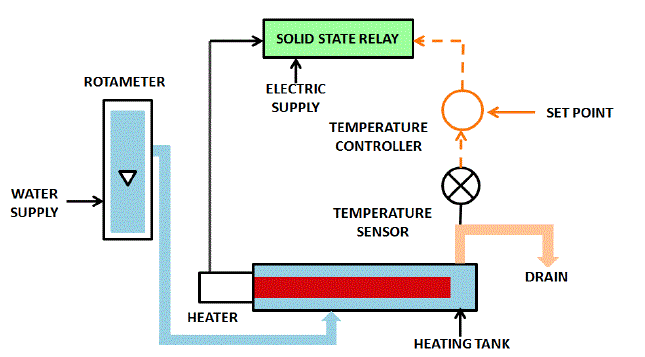
| Temperature control trainer is premeditated for understanding the fundamental temperature control principles. The process setup consists of heating tank fixed with SSR controlled heater for on-line heating of the water. The flow of water can be manipulated and measured by rota meter. Temperature sensor (RTD) is used for temperature sensing. The process parameter (Temperature) is controlled by microprocessor based digital indicating controller which manipulates heat input to the process. These units along with necessary piping and fitting are mounted on support frame designed for tabletop mounting. The controller can be connected to computer through USB port for monitoring the process in SCADA mode. Fig. 2.1 show Process diagram of Temperature control Trainer. Table 2.1 shows that some valuable Specification of Temperature Control Trainer |
DERIVATION OF TRANSFER FUNCTION
|
| In general, a transfer function relates two variables in a physical process; one of these is the cause (forcing function or input variable) and the other is the effect (response or output variable) [1]. It provides valuable insight into process dynamics and the dynamics of feedback systems. This temperature process is a first order dead time process. So it can be defined as |
 (2) (2) |
| Where, |
| K = Gain constant (B/A) |
| θ = Delay time |
| Τ = Time constant |
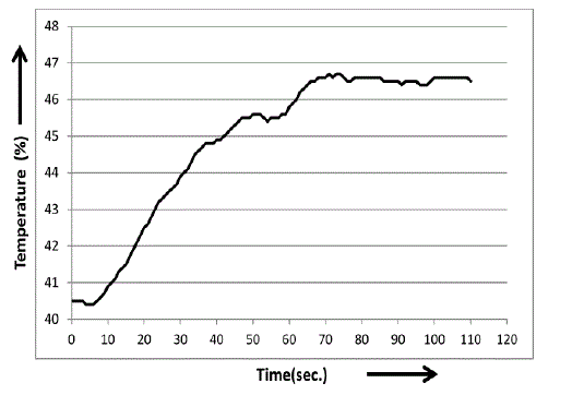
| In open loop response, set controller input value and obtain the initial and final steady state value shows in Table 4.1. And note down change of process value with respect to time from initial steady state to final state. Its show in figure 4.1 |
| From Open loop Response, by using those parameter, Delay time ( ) = 7 sec, Gain (K) = 1.1481, Time constant = 35 sec obtain from the graph. eqn. (3) show that open loop response of real time temperature process. |
 (3) (3) |
APPROACH TO PID TUNING
|
| Tuning a control loop is the adjustment of its control parameters (gain/proportional band, integral gain/reset, derivative gain/rate) to the optimum values for the desired control response [2]. Generally stability of response is required and the process must not oscillate for any combination of process conditions and set points [3]. The following PID tuning formulas are considered: |
| A. Ziegler–Nichols (Z–N) method (1942): It’s depends on the ultimate gain Ku and the ultimate period Tu. . |
| B. Tyreus-Luyben tuning method (1992): It’s depends on the ultimate gain Ku and the ultimate period Tu. |
| C. Cohen–Coon (C–C) method (1953): Based on Process reaction curve. A model with one tangent and point is derived first to tune the PID controller. |
| D. Shinskey tuning method (1990): This method be worked under the conduction (τ/θ =1.6). |
| E. Fruehauf tuning method (1990): This method be worked under the conduction (θ/τ <0.33). |
| F. St. Clair tuning method (1987): Based on Process reaction curve. |
| Tuning parameters of PI and PID controller are show in Table 4.1 & 4.2 |
TIME DOMAIN SPECFICATION
|
| The performance of a control system is typically measured in provisions of its response to a step input. So that by calculating time domain specification of a response its easy analysis. By comparing with various tuning methods in PI controller Tyreus-Luyben and Fruehauf tuning methods shows good response to this system. It shows in table 5.1. In comparisons of PID controller explain in table 5.2 Tyreus-Luyben show good response. |
PERFORMANCE ANALYSIS
|
| The integral error is generally accepted as a good measure for system performance [1]. It is useful to have criteria that put little weight on the initial error. These integrals are finite only if the steady- state error is zero. Unlike simple criteria that use only isolated characteristics of dynamic response, the criteria of the category are based on the entire response [9]. The followings are some commonly used criteria based on the integral error for a step set point or disturbance response |
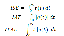 (4) (4) |
| Where, e(t) = ysp(t) – y(t) is error of response from the desired set point. |
| Comparison of integral error of various tuning methods for PI controller and PID controller shows in Table 6.1 and Table 6.2. Here also that Tyreus-Luyben tuning method shows that minimum error for both PI and PID controller. |
SERVO AND REGULATION PROBLEM
|
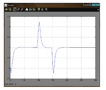
| In feedback close loop system; Servo control loop is one which responds to modify in set point where as the load disturbance value remains stable show in figure 7.1. The set point may be changed as a function of time (typical of this are batch processes), and therefore the controlled variable must follow the set point. A regulatory control loop is one which responds to a modify in load disturbance value, bringing the system back to steady state where as the set point value remains stable show in figure 7.2. Regulatory control is by distant more common than servo control in the process industries. |
SIMULAION RESULT
|
| The MATLAB coding of the simulator is design various types of function block [6]. The coding is totally based on the concepts of PID tuning. It is that much efficient to analysis any system and give step response using P, PI, &PID controller. |
| A. Step Response Of Transfer Function in MATLAB Program : |
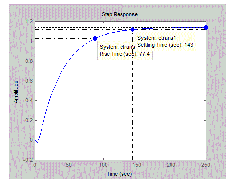
| Figure 8.1.1 shows that step response of open loop system for transfer function of |
 (3) (3) |
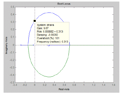
| B. To Find Ultimate Gain Ku and Ultimate Time Period Tu in MATLAB Program Using Root Locus Plot |
| For same transfer function from figure 8.2.1 we get value that shows in Table 8.2.2 |
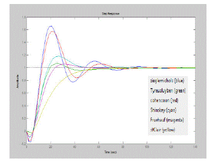
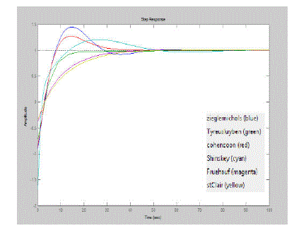
| C. Response of PID Controller in both MATLAB Program and Simulink Diagram |
| D. Simulink diagram of servo problem and regulatory problem |
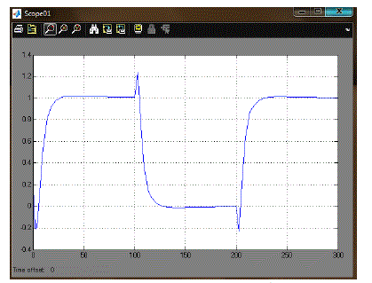
| From these analyses of various tuning method we proposed that Tyreus-Luyben tuning methods show the stability proper response. Then apply tuning parameter of Tyreus-Luyben in servo and regulator problem. Figure 8.4.3 and Figure 8.4.4 are shows that analysis of the stability of the system. Here the MATLAB Simulink diagram for the for the servo and regulator problem is show in Figure 8.4.1 and Figure 8.4.2 Since the set point has to be varied the number of step input is declared by giving the different inputs and different sampling time. The value is given as 1,-1 &1. And the output is controlled. For the disturbance rejection the load has to be varied. So the different types of load are given before the output. The disturbance is declared as 1,-1. And the resultant output is given below. |
IN REAL TIME IMPLEMENTATION
|
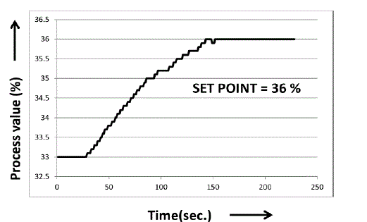
| Figure 9.1 shown is the real time response of temperature kit process value. Here tuning parameter of Tyreus- Luyben tuning method value is substituted. The set point is given as 36, when the process variable is less than that of the set point the output reaches maximum value of 100%. After process value reach the set point value controller output will decrease. |
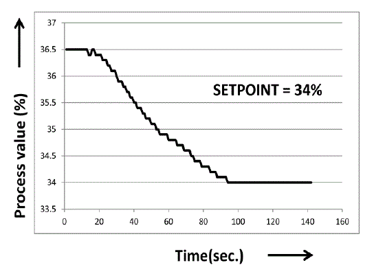
| Figure 9.2 shows that set point variation of real time implementation. The old set point value is 36.5 and new set point value is 34. Output response shows that proper controlled comeback. |
CONCLUSION
|
| In this paper we proposed comparative novel methods of various types of PID tuning for temperature process and result of comparison also elucidated. A comprehensive comparative study of various types of tuning methods tested with simulation under different conditions show that better analysis. Simulation results have been given to show the performance of the method. The proposed tuning method is superlative and show good performance in apply with real time implementation. |
| |
Tables at a glance
|
 |
 |
 |
 |
 |
| Table 2.1 |
Table 3.1 |
Table 4.1 |
Table 4.2 |
Table 5.1 |
| |
 |
 |
 |
 |
 |
| Table 5.2 |
Table 6.1 |
Table 6.2 |
Table 8.1 |
Table 8.2.2 |
|
| |
Figures at a glance
|
 |
 |
 |
 |
 |
| Figure 2.1 |
Figure 3.1 |
Figure 7.1 |
Figure 7.2 |
Figure 8.1.1 |
| |
 |
 |
 |
 |
 |
| Figure 8.2.1 |
Figure 8.3.1 |
Figure 8.3.2 |
Figure 8.4.1 |
Figure 8.4.2 |
| |
 |
 |
 |
 |
| Figure 8.4.3 |
Figure 8.4.4 |
Figure 9.1 |
Figure 9.2 |
|
| |
References
|
- George Stephanopoulos “Chemical Process Control: An Introduction to Theory and Practices”- 1st edition, Person Education, 1984.
- A. O’dyer “PI and PID controller tuning rules for time delay processes: a summary” Technical Report AOD-00-01, 1stedition, School of ControlSystems and Electrical Engineering, Dublin Institute of Technology, Ireland,2000.
- Dingyu Xue, YangQuan Chen, and Derek P. Atherton, “Linear Feedback Control",-1st edition, Society for Industrial and Applied Mathematics, 2007.
- Donald R. Coudhanowr, “Process System Analysis and Control”, 2nd edition, McGRAW Hill International Edition,1991.
- Hari Om Bansal, “PID Controller Tuning Techniques: A Review”, C World Academic Publishing, Journal of CET, Volume 2, pp. 168-176, 4 October2012.
- Susmita Das, “Study on Different Tuning Approach with Incorporation of Simulation Aspect for Z-N Rules”, International Journal of Scientific andResearch Publications, Volume 2, Issue 8, August 2012.
- Saeed Tavakoli & Mahdi Tavakoli, “Optimal Tuning of PID Controllers for First Order Plus Time Delay Models Using Dimensional Analysis”, IEEE4th International Conference on Control and Automation (ICCA’03), Montreal, Canada, Volume 4, pp. 942 – 947, 10-12 June 2003.
- Jianghua Xu, Huihe Shao, “A Novel Method of PID Tuning for Integrating Processes”, 42nd IEEE Conference on Decision and Control, Maui, HawaiiUSA, pp. 139 - 142 ,December 2003
- K. Astrom and T. Hagglund, “PID Controller, Theory, Design and Tuning”, 2nd edition, Instrument Society of America,1995.
- Wen Tan, Comparison of some well-known PID tuning formulas, Computers and Chemical Engineering, no. 30,pp. 1416–1423, 2006.
- K. J. Åström and B. Wittenmark, Lecture 19: Servo and regulator problems, reference values and integrators.
- S.Katti. (2010) IATED Homepage on Digital Library.[Online].Available: http:// library.iated.org/view/KATTI2011SIM”
- Leature 19. Homepage on IVT.NTNU. [online]. vailable:http://www.ivt.ntnu.no/imt/courses/tmr2/slides/slides_files/f19.pdf
|