This paper focuses on the vector control of a BLDC motor with two different concepts of Pulse Width Modulation- the Sinusoidal PWM and the Space Vector Modulation strategy. The paper deals with the basics of a BLDC motor, its dynamic modeling and its speed control using two different strategies of Pulse Width Modulation. The vector control is one of the methods used in variable frequency drives or variable speed drives to control the torque (and thus the speed) of three-phase AC electric motors by controlling the current. The results prove that the Space Vector Modulation technique helps to improve the performance and thus the efficiency of the system.
Keywords |
| BLDC motor, Vector control, Space Vector PWM. |
INTRODUCTION |
| The Brushless DC Motors are synchronous motors which are powered by DC electric source via an inverter or switching
power supply which produces an AC electric signal to drive the motor. Its stator consists of ac winding which is either star
or delta connected and the rotor consists of Permanent Magnets. BLDC motors are used in industries such as Appliances,
Automotive, Aerospace, Consumer, Medical, Industrial Automation Equipment and Instrumentation. BLDC motors have
many advantages over brushed DC motors and induction motors. A few of these are: |
| 1. Higher torque to weight ratio |
| 2. More torque per watts (increased efficiency) |
| 3. Increased reliability |
| 4. Reduced noise |
| 5. Longer lifetime |
| 6.Elimination of ionizing sparks from commutator |
| 7. Reduced EMI |
| 8. Easier cooling by conduction |
| 9. Better power factor. |
| The speed of a motor can be controlled using open loop control. But accurate speed control is necessary in various
applications, which can be achieved by closed- loop speed control only. Vector control is an important technology for
motor systems, particularly those using Permanent Magnets (PM). It provides an efficient way to control a synchronous
motor in adjustable speed drive applications that have quickly changing loads, and can improve the power efficiency of AC
induction motor, especially at lower speeds. This does not mean that the vector control technique can solely be used for the
power efficiency of induction motors. The Brushless DC motors are by themselves, very efficient (up to 96%), but by
implementing vector control in BLDC motors, the torque ripple can be reduced to a great extent, resulting in an improved
performance. In the past few years the field of controlled electrical drives has undergone rapid expansion due to the
technological improvements in semiconductor devices. New electronic microprocessors and DSPs which provide amazing
computational speeds have enabled the development of effective vector controlled AC drives with lower power dissipation
and more accurate control. |
| The modelling of BLDC motor is based on the assumption that the iron and stray losses and also the induced currents due
to stator harmonic fields are neglected. The motor is considered to be a three phase motor. |
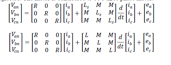 |
| Where ia, ib and ic are the stator currents per phase. The induced emfs are ea, eband ec which are assumed to be trapezoidal
with a peak value of Ep, derived as |
 = λpωm = λpωm |
| Where N is the number of conductors in series per phase, v is the velocity, l is the length of the conductor, r is the radius of
the rotor bore, ωm
is the angular velocity and B is the flux density of the field in which the conductors are placed. |
| The flux density B is solely due to the rotor magnets. The product (Blr), denoted as φa has the dimensions of flux and is
directly proportional to the air gap flux φg . |
 |
| The product of flux and the number of conductors in in series has the dimension of flux linkages and is denoted by λp
.
Since it is proportional to the flux linkages by a factor of
1/Π
, it is referred to as modified flux linkages. |
| By the Laplace Transform method, the voltage of each phase can be written as |
 |
| From the above equation we obtain the per- phase current as |
 |
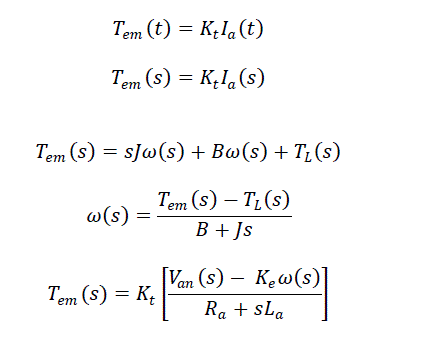
| Mechanical equation |
 |
| Where Tem(t) is the developed electromagnetic torque,ω(t) is the rotor angular velocity, B is the viscous friction constant, J
is the rotor Moment of Inertia and TL is the load torque. |
 |
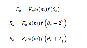
| The back emfs can be written as |
 |
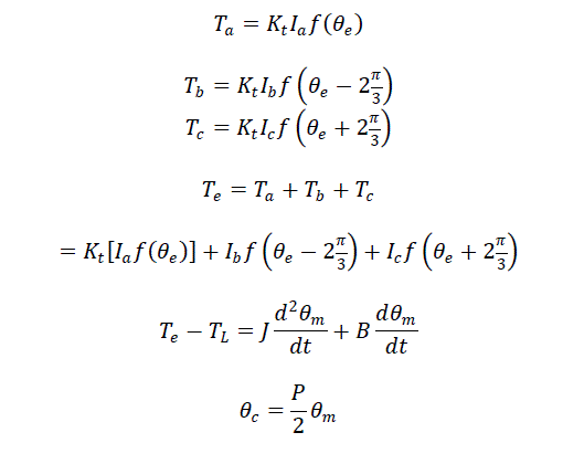
| The torque can be written as |
 |
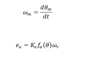 |
| Phase induced emf |
 |
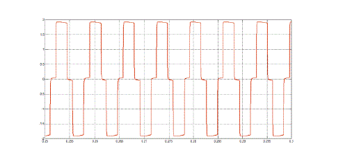
| The induced emfs are of a trapezoidal shape. It can be observed that the phase voltage equations are identical to the
armature voltage equations of a dc machine. This is one of the reasons for naming this machine as Permanent Magnet
Brushless DC Machine, even though it is an AC machine. |
VECTOR CONTROL |
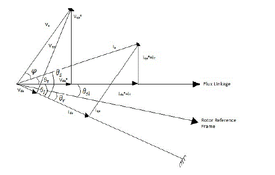
| The oscillations in the air gap flux linkages would result in oscillations in the electromagnetic torque, which would reflect
as speed variations, which is undesirable. Separately excited dc drives are simpler in control as they independently control
flux, which when maintained constant, contributes to an independently controlled torque. This control strategy can be
applied in the case of ac drives also, known as Vector Control. |
| The motor controlled through a voltage source inverter. It is coupled to a dc tacho, the output of which is the actual rotor
speed ωr. This is compared with the reference speed ωr*
. The error is amplified and limited to produce the q- axis reference
current. This is compare with the actual q- axis current from the motor and the error is amplified and limited with a PI
controller. Similarly the d-axis current reference, which is taken as zero is compared with the actual d- axis current and the
error is again amplified and limited. These currents are transformed to the a-b-c reference frame and then provided as inputs
to the Pulse Width Modulation circuit. The paper aims at a comparative study of the responses for the two different
methods of Pulse Width Modulation, the Sinusoidal PWM and the Space Vector PWM when they are used in the Vector
controlled BLDC motor. |
COMPARISON OF SINE PWM AND SPACE VECTOR PWM IN A VECTOR CONTROLLED BLDC
MOTOR |
| A.Sinusoidal PWM |
| Pulse width modulation is the process of modifying the width of the pulses in a pulse train, in direct proportion to a small
control signal; the greater the control voltage, the wider the pulses become. By using a sinusoid of the desired frequency as the control voltage for a PWM circuit, it is possible to produce a high power waveform whose average voltage rises
sinusoidally in a manner suitable for driving ac motors. |
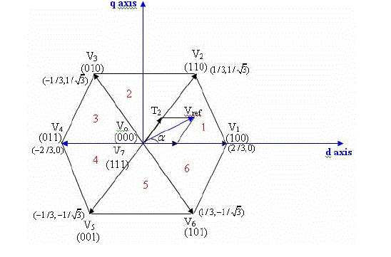
| B.Space Vector PWM |
| The main aim of any modulation technique is to obtain variable output having a maximum fundamental component with
minimum harmonics. Space Vector PWM (SVPWM) method is an advanced; computation intensive PWM method and
possibly the best techniques for variable frequency drive application. Because of the constraint that the input lines must
never be shorted and the output current must always be continuous, a voltage source inverter can assume only eight distinct
topologies. Six out of these eight topologies produce a non-zero output voltage and are known as non-zero switching states
and the remaining two topologies produce a zero output voltage and are known as zero switching states. |
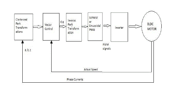
| Figure 4 depicts the vector control block diagram of a BLDC motor implementing Space Vector PWM or Sinusoidal PWM.
The actual speed of the motor is compared with the speed reference. The error is given to a PI controller and limited. The
resulting signal is called the torque reference current
. This is compared with the actual current , obtained from the
motor after Clarke and Park’s transformations of currents , , the stator currents. The current is compared with
a zero reference current. The errors are again amplified and limited and the outputs are given to the PWM block. |
| The comparison between Sinusoidal PWM and Space Vector PWM clearly reveals that the torque and hence the speed
fluctuations, the current waveforms are better for the Space Vector Modulation when implemented in a Vector Control
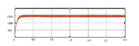
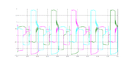
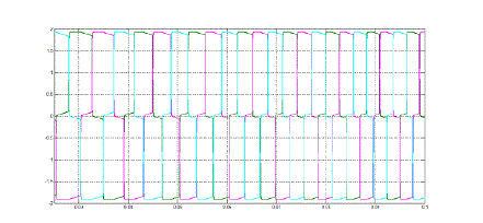
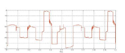
circuit. Figures 5 and 6 show the speed waveforms of Sinusoidal PWM and SVPWM respectively. A reference speed of 1500 is given as input.The speed fluctuations are more in sinusoidal PWM. Similarly the current waveforms are shown
from Figures 7 to 10. This also reveals that the current waveforms are better for SVPWM. |
CONCLUSION |
| In this paper, the comparison of current and speed waveforms are done when Sinusoidal PWM and SVPWM are
implemented in the Field Oriented Control of Brushless DC motor. The simulation results reveal that the fluctuation in
speed and torque are less when the Space Vector Modulation strategy is implemented in the vector controlled motor. Thus
it can be concluded that the overall performance of a motor drive system is improved when Space Vector Modulation
technique is used in the system. |
| |
Figures at a glance |
 |
 |
 |
 |
 |
| Figure 1 |
Figure 2 |
Figure 3 |
Figure 4 |
Figure 5 |
| |
 |
 |
 |
 |
 |
| Figure 6 |
Figure 7 |
Figure 8 |
Figure 9 |
Figure 10 |
|
| |
References |
- R. Krishnan, “Electric Motor Drives Modeling, Analysis and Control,” Prentice Hall 2001.
- Zhenyu Yu, Arefeen Mohammed, IssaPanahi. 1997, “A Review of Three PWM Techniques” Proceedings of the American Control ConferenceAlbuquerque, New Mexico. pp. 257-261.
- AnshumanTripathi, Ashwin M. Khambadkone, “Torque Ripple Analysis and Dynamic Performance of a Space Vector Modulation BasedControl Method for AC-Drives”, IEEE Transactions On Power Electronics, vol. 20, no. 2, March 2005.
- Wenxi Yao, Haibing Hu, and Zhengyu Lu, “Comparisons of Space-Vector Modulation and Carrier-Based Modulation of Multilevel Inverter”,IEEE Transactions On Power Electronics, vol. 23, no. 1, January 2008.
- Joseph P John, Dr. S. Suresh Kumar, “Space Vector Modulation based Field Oriented Control Scheme for Brushless DC Motors” ,PROCEEDINGS OF ICETECT 2011
- Bimal K. Bose, Modern Power Electronics and AC Drivers. Penitence.
|