ISSN ONLINE(2319-8753)PRINT(2347-6710)
ISSN ONLINE(2319-8753)PRINT(2347-6710)
Swagat Pati#1, Narendra Kumar Jena#2, Santosh Acharya#3
|
| Related article at Pubmed, Scholar Google |
Visit for more related articles at International Journal of Innovative Research in Science, Engineering and Technology
Speed control of permanent magnet synchronous machines for reliable speed wind energy systems has always been a challenging task. But with the development of vector control strategies the speed control process has been easily achievable. In this paper the control of speed and torque of a PMSG is discussed. Vector control strategies have been implemented for the PMSG control. The PMSG is modeled in synchronous rotating reference frame. The whole control scheme is modeled using Matlab/Simulink and the results are discussed
Keywords |
| Permanent magnet synchronous generator(PMSG), Vector control scheme, PI controllers. |
INTRODUCTION |
| In the advent of the advanced and proficient technologies the wind Energy Conversion System (WECS) has penetrated well in the energy market. Although Induction Generators are the work horse of the WECS, but to achieve high power density with reducing size, Permanent Magnet Synchronous Generators (PMSG) are used. The drawbacks of these machines are more expensive and prone to demagnetization. PMSG based WECS are of two types, such as direct driven and indirect driven. As in synchronous generator multiple pole design is possible, hence it is employed in the gearless operation. In case of direct driven PMSG, it needs less maintenance because there are no gear drives. In the recent years it has become a promising source of Clean and renewable Energy. But WECS has a major drawback that the wind behavior is highly changing, so constant voltage and frequency generation is not possible with fixed speed wind turbines. But with advancement in power electronic converters, variable speed wind power generation has become possible. Variable speed wind WECS consists of two measure blocks. They are |
| (1) Control of the generator for transient and steady state performance improvement [1-6]. |
| (2) Control of the Grid-side converter for supplying power at constant voltage and frequency [1-6]. |
| The choice of generator for a WECS is very vital task. Induction generator are used extensively in WECS for their advantages that they are robust, efficient and cheaper. But they suffer from a drawback that they canâÃâ¬ÃŸt generate flux for power generation .So either they have to be grid connected or a capacitor bank is needed to make the machine self excited. Again as they draw reactive power from the grid they have a low working power factor [11, 12].Although induction generators are the main work horse of WECS, but to achieve high power density PMSG are used. In PMSG the rotor is provided with permanent magnet so there is no need of rotor winding, so no rotor loss occurs in the machine. To maintain a constant air gap flux there is no need of magnetizing current hence the working power factor of PMSG is high. Although these machines have drawbacks that they are costly and less efficient than induction machines and they are prone to demagnetization, but can provide a promising and high quality power to the grid. |
| As mentioned earlier in variable speed wind power generation the control of the generator plays a vital role in maximum power extraction from wind[11, 12].Many control structures have been recently developed for the control of PMSG, such as Vector control[7-10],Direct Torque control, Direct power control, In vector control the active and reactive power are decoupled and controlled independently[7-10].Direct Torque control strategy concentrates on the control of the stator flux vector with respect to the rotor flux, such that desired operating conditions can be met[9,10]. |
| In this paper the modeling and dynamic behavior of direct driven variable speed medium power based PMSG has been proposed. For controlling the PMSG the generator side converter is controlled which results in the control of speed/torque of the generator and also the control of the active and reactive power flow to the grid. For the control of machine side converter vector control strategy employing PI controllers is implemented. The whole system is simulated using Matlab/Simulink environment and results are analyzed. |
II. SYSTEM OVWRVIEW |
| The wind energy conversion system, as shown in Fig.2 comprises of wind turbine, PMSG, PWM converter and converter control system. |
| The output of PMSG is not suitable for use because it generates power at variable voltage and frequency due to variable wind speed. So it is converted to constant DC voltage at the DC link to be directly used as a dc source or for storage or further inverted into AC and synchronized to a grid. A vector controlled IGBT based inverter is used to regulate the speed, active power and reactive power of the PMSG during the wind speed variation |
III. M ODELLING OF PMSG |
| Generally machine models are expressed in d-q reference frame, because if it is modeled in „abcâÃâ¬ÃŸ reference frame then the equations describing the machine ,involves time varying inductances, so it is complex to solve by any analytical method. To alleviate this shortcomings ,by parkâÃâ¬ÃŸs transformation the time varying machine equations are transferred to time invariant( dc)equations in a synchronously rotating frame. In this paper d-q reference based equations have been described. |
 |
 |
 |
V. CONROL STRUCTURE |
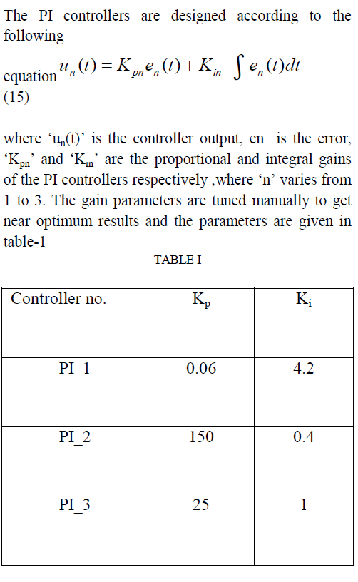
| To get rid of the demerits of Scalar control, vector control is used profusely. In this paper the d-axis component of current is aligned with flux vector and q-axis component current is 90 degree ahead of it. The d-axis current controls the reactive power and q-axis current controls the active power. So the active and reactive power are decoupled and can be controlled easily and independently. Basically in this paper two current control loops has been demonstrated as shown in the Fig.2. which are controlled by conventional PI controller. Here the rotor angle θ and rotor speed ω has been traced from the generator and converted to its electrical equivalent. The error signal of the measured speed and reference speed is processed through a PI controller to get ïÃâ¬Ãª qs i .The d-axis generator current reference is set to, ïÃâ¬Ãª ds i =0. Finally the d-q component of the voltage vector which controls the d-q current of generator is passed through PI controllers. |
 |
 |
VI. SIMULATION AND RESULT ANALYSIS |
A. Dynamic response with the step change in reference speed. |
| The speed versus time characteristic has shown in Fig. 3. The oscillation damps out within 0.4 sec.The system has been subjected to a step change in speed from 314rad/sec(electrical) to 200rad/sec(electrical) at time 3 seconds. |
 |
| During this speed variation the mechanical torque has been kept constant. As it is a medium power machine, - 25 Nm mechanical torque has been provided. And it has been observed that variation of torque is for a transient period of time and again the torque regains its previous set value of -25Nm after a time of 0.4 second as shown in Fig.4. |
 |
| Fig.6 Power factor during step change in reference speed |
| Fig.7 & Fig.8 show that the inverter phase voltage and phase current of PMSG respectively. And from these figures it is evident that the inverter frequency is reduced when the speed is reduced at the time 3 sec. |
| From the Fig.5 it can be seen that when the speed was 314rad/sec (electrical) i.e. the machine runs at synchronous speed the air gap flux is same as the flux of the rotor. But when the reference speed command is reduced to 200rad/sec (electrical) at time 3 sec, the air gap) flux needs to be increased to reduce the speed. The rotor is in capable of increasing the air gap flux. So the machine draws reactive power from the grid for generation of extra air gap flux for reducing the speed. This is clear from the Fig.5, the reactive power before time 3 sec is zero, but after 3 seconds the reactive power becomes positive is: reactive power is drawn from the grid. Again as the speed reduces the torque remains constant so active power also reduces from - 1050 watts to -650 watts |
 |
 |
B. Dynamic response with step change in turbine Torque. |
| Again this system has been subjected to a step change in turbine torque at time 3 sec and the performance of the system is simulated.The turbine torque is changed from - 25Nm to -40Nm at 3 sec.The speed response of the system can be seen from the Fig.9.It is evident from the figure that the speed deviates from its reference valuefor 0,3 sec due to the sudden changein turbine torque,but again settles down at the reference value . |
 |
| The electromagnetic torque response of the PMSG has been illustrated in the Fig.10 and torque varies from - 25Nm to -40Nm. |
 |
| The excursion of active and reactive power has shown in the Fig.11.As the torque increases the active power fed to the grid increases. When the turbine torque Fig.10 |
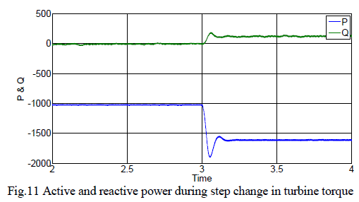 |
| increases it tends to accelerate the machine but the machine has to be kept the reference speed. This is possible by increment in the air gap flux, so the PMSG draws extra reactive power from the grid to generate the extra flux and to maintain the speed at its reference value. So the reactive power increases, which can be seen from the Fig.11. |
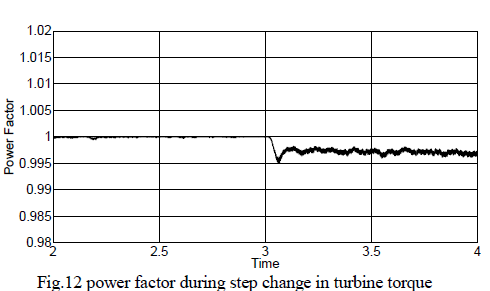
| The Fig.12 gives the power factor of the PMSG during variable torque conditions. Initially the power factor was unity but as the turbine torque increased the reactive power increased so the power factor decreased to a value less than unity. |
 |
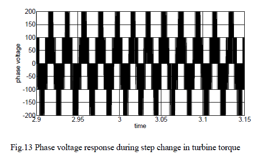
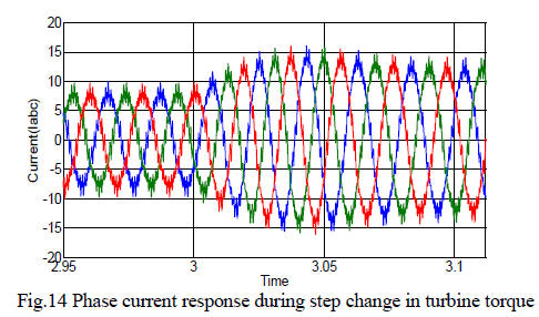
| The phase voltage and phase current of inverter is shown in the Fig.13 & Fig.14.From the Fig.14,it is evident that the current increases as the torque increases and from the Fig.13 it is clear that the frequency of the supply voltage remains constant with the variation of torque keeping the speed constant. |
 |
 |
VII. CONCLUSION |
| The PMSG and vector control strategies has been successfully modeled in this paper. The tuning of PI controllers has been done manually which means that the outputs shown are near optimum results. The perfect decoupling between speed and torque is achieved by the vector control strategy which shows that the vector control strategy is an efficient and fast scheme which is capable for enhancing the performance of PMSG based wind energy conversion system. The working power factor of the PMSG based wind energy conversion system is better than that of induction machine based WECS, which makes PMSG an efficient alternative for induction machine, for wind energy conversion system applications. |
 |