Keywords
|
| DC/DC converter, Drive applications, triangular pulse width modulation, coupled inductor. |
INTRODUCTION
|
| With the increasing demand for high voltage in the industrial applications, efficient DC/DC converter with high step up voltage gain is widely used. This need proliferates in designing an efficient DC/DC converter with reduced components, filter size and cost which will lead the converter for easy public marketing. Usually, the boost DC/DC converter operates at high step up voltage gain at high duty cycle. But unfortunately the passive elements present in the circuit become an obstacle for achieving high step up voltage gain. Hence in order to improve the efficiency of the converter, energy stored in the passive components like capacitor and the coupled inductor [1], [2], must be efficiently utilized by the system. Thus this paper proposes a transformerless high gain step up DC/DC converter [3]–[6] with practical and economical considerations. |
| Permanent Magnet DC (PMDC), [7] motors are widely used in a range of applications, from battery powered devices like wheelchairs and power tools, to conveyors and door openers, welding equipment, X-ray and tomographic systems, and pumping equipments. These motors have the ability to produce high torque at low speed. Its design yields a smaller, lighter, and energy efficient motor. The PM motor’s field has a high reluctance (low permeability) that eliminates significantarmature interaction. This high reluctance yieldsa constant field, permitting linear operation over the motor’s entire speed-torque range.Applications such as amusement drives, pump drives etc. requires high DC voltage. |
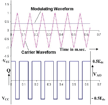
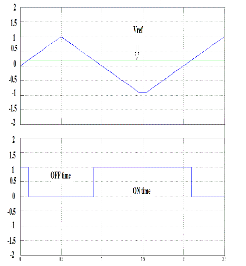
| In Triangular PWM, the output voltage is controlled by varying the duty cycle. The duty cycle in turn is controlled by varying the reference and the carrier wave signals. In this method a constant reference signal Vref is compared with the triangular carrier wave signal. The peak magnitude is limited by the peak carrier wave signal. Among all renewable energy sources, solar power systems [8]-[10]attract more attention because they provide excellent opportunity to generate electricity while greenhouse emissions are reduced. The only way of generating electricity from solar energy will be PV cells or panels. Temperature, insulation,Spectral characteristics of sunlight, dirt,shadowetc., are the main factors to be considered for the efficiency of the solar cells. |
| The PV cells aremade up of silicon, which is also used in computer"chips". The radiation produced from the sun will be converted into direct current (DC) by thisPhotovoltaic process. This point is known asmaximum power point (MPP). The MPPT [11] is the efficient way to track the maximum available output power of the PV system. |
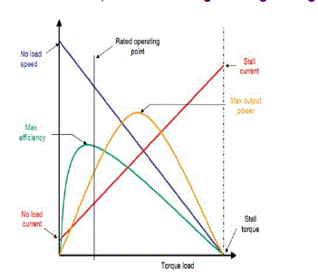
| The performance curve of PMDC motor is shown in Fig. 1. In operation, with a constant armature voltage, as speed decreases, available torque increases. Speed is controlled by varying the voltage applied to the armature. PMDC motors use a mechanical commutation scheme to switch current to the armature winding. Feedback devices sense motor speed and send this information to the control to vary its output voltage up or down to keep speed at or near the set value. |
PROPOSED CIRCUIT DESCRIPTION
|
| A. Circuit Configuration |
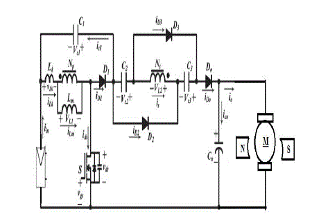
| The circuit configuration of the proposed converter is shown in Fig.2. The main components of the proposed circuit are main switch S, clamping capacitor C1, clamping diode D1, one coupled inductor Np and Ns, two capacitors C2 and C3,two diodes D2 and D3, Output capacitor Co, and Output diode Do. This circuit is powered by a PV panel and it drives a PMDC motor load. The equivalent circuit model also includes leakage inductance Lk and magnetizing inductance LM. |
| The leakage energy stored in the coupled inductor is recycled to the capacitor and hence the voltage stress across the switch is reduced. This feature of the proposed converter increases the perfornance and thus the efficiency of the converter. |
| B.Operating principle of the Proposed Converter |
| When switch is ON, Vin charges LM and in turn the secondary side of the coupled inductor. Similarly, when the switch is OFF, the energy stored in LM is discharged through the secondary side of the coupled inductor. Inorder to reduce the voltage across the switch S, the capacitors C2 aand C3 discharges in series whereas they charge in parallel during the turn OFF and turn ON process respectively. |
| C.Continuous Current Mode operation of the proposed converter |
| There are five operating modes in each switching cycle. Each operating mode is discussed below in detail. |
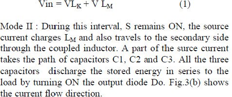
| Mode I : In this mode, S is ON. As mentioned in the previous topic,Vin charges LM and the secondary side of the coupled inductor. Thus the secondary side current is charges C2 and turns ON the diodes D2, D3 and the capacitor C3. The output capacitor Co supplies the load. The current flow is shown in Fig.3(a). The expression for the input voltage can be written as, |
 |
| Mode II : During this interval, S remains ON, the source current charges LM and also travels to the secondary side through the coupled inductor. A part of the surce current takes the path of capacitors C1, C2 and C3. All the three capacitors discharge the stored energy in series to the load by turning ON the output diode Do. Fig.3(b) shows the current flow direction. |
| Mode III : As soon as, the three capacitors completely discharge to the output voltage, S is turned OFF. The source current thus flows through the coupled inductor, LM, and the parasitic capacitor Cds of the switch S. Thus ZVS is achieved for the switch S. The output capacitor Co supplies the load. Fig.3(c) represents this mode. |
| Mode IV : In this mode, the moment the parasitic capacitor Cds gets fully charged, the source current now flows through the LM, coupled inductor, D1, C2,C3,Do and the load. Further the energy stored in the leakage inductor Lk is recycled through the clamping capacitor C1. The circuit representation for the above explanation is shown in Fig.3(d). |
| Mode V : During this interval, the supply voltage is detached. The recycled energy of Lk flows through LM. The current flowing through also flows through the coupled inductor. This charges the capacitors C2 and C3 in parallel. The secondary current also flows through the diodes D2 and D3. Co supplies the load. At the end of this mode switch S turns ON and the cycle continues. Fig.3(e) shows the circuit diagram representation of this mode. |
MODELING OF MOTOR AND SOURCE
|
| A. Modeling of Permanent Magnet DC motor The following are the PMDC motor equations. |
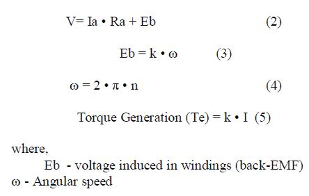 |
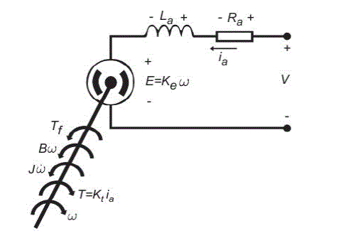
| Factor k depends on motor design features (number of winding turns, permanent magnet strength, air gap distance, rotor diameter, rotor length). The PMDC motor directly provides rotary motion and, coupled with wheels or drums and cables, can provide transitional motion. The electric circuit of the armature and the free body diagram of the rotor are shown in the following Fig.4.1 |
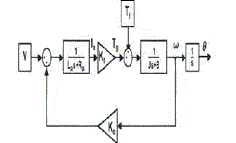
| The motor torque, T, is related to the armature current, ia , by a constant factor Kt . The back emf, E, is related to the rotational velocity by the constant factor Ke as in the following equations: |
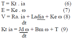 |
| The modeling of the PMDC motor is drawn using the above equations as shown in Fig.4.2. |
| B. Modeling of Photovoltaic array system |
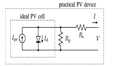
| The PV panel module physically moves to point directly at the sun and which the MPPT is not a mechanical tracking system. The battery is directly connected to the module and it is charging a discharged battery. Hence the module will be operated at battery voltage. The equivalent circuit of the PV cell in shown below in The basic equation of I – V characteristic of the ideal PV is mathematically described from the theory of semiconductors |
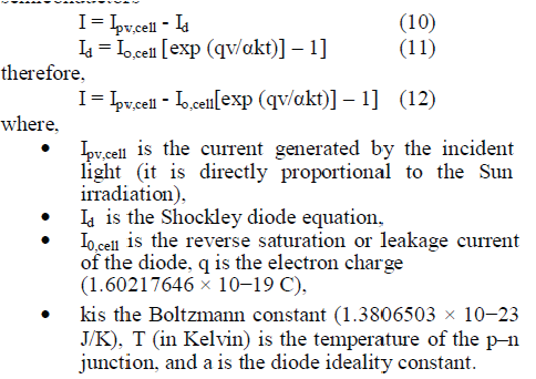 |
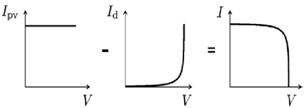
| The Fig.5.2 shows the origination of the I – V curve for the equation (12). Practical arrays are made up of multiple modules. The observation of the characteristics at the terminals of the PV array requires the inclusion of additional parameters to the basic equation. |
 |
| where, |
| V = NskT/q is the thermal voltage of the array with Nscells connected in series. |
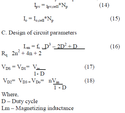
| RS& RP is the equivalent series and parallel resistance of the array. The cells connected in parallel which increases the current and the greater output voltage will be produced by the cells connected in series. The Np parallel connections of cell composes the array, the PV and saturation currents may be expressed as, |
 |
TRIANGUALR PULSE WIDTH MODULATION
|
| The magnitude of the dc modulating signal is constrained to remain between the minimum and maximum magnitudes of the triangular carrier signal. Now, the high frequency triangular carrier waveform is compared with the dc modulating signal and the comparator output is used to control the switch. The Fig.6 shown below explains the triangular PWM generation. |
DISCUSSION OF SIMULATION RESULTS
|
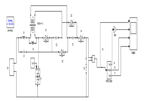
| The performance of the proposed converter is illustrated using PMDC motor load. The performance is studied by using Matlab simulation. The simulink model of the proposed converter with the PMDC motor load are shown in Fig.6.1and Fig 6.2 respectively. |
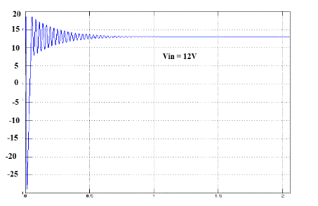
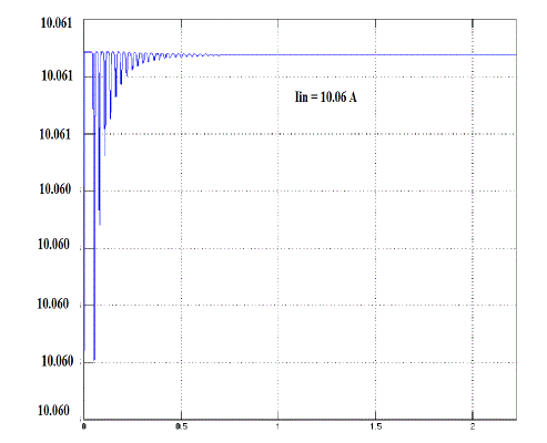
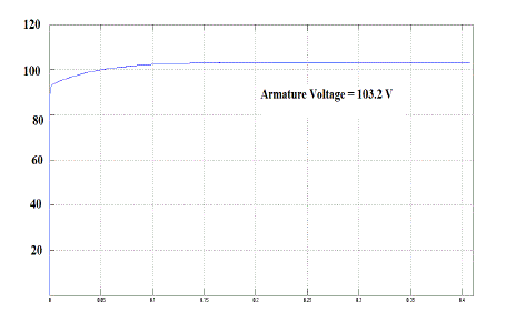
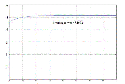
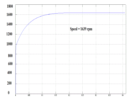
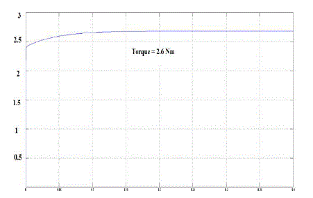
| The resultant armature voltage, armature current and torque is shown if Fig.6.5,6.6 and 6.8 respectively. Pulses for the gate generated using triangular pulse width modulation technique are shown in Fig 6.4. A 0.5 HP, 1640 rpm PMDC motor is driven by using a 12 V solar panel. The armature voltage and the current obtained are from this proposed system are 100V, 5 A. |
CONCLUSION
|
| The performance of the DC/DC converter is improved in this paper by effectively utilizing the energy stored in the passive elements. This converter is powered by the renewable of energy i.e. solar. The proposed system can be efficiently utilized in high speed drive applications. In this case, the proposed system is made to drive a PMDC motor load. The converter receives an input voltage of 12V from the solar panel, and in turn produces 100V/ 5A driving a PMDC motor load of 0.5 rating. Further, soft switching technique with Triangular pulse width modulation strategy reduces the switching losses and stress thereby improving the efficiency further. Moreover as the energy stored in the passive elements are effectively utilized, the overall losses reduces considerably there adding the efficiency percentage. And also this proposed system is cost effective and can be used in wide range of drive applications. |
Figures at a glance
|
 |
 |
 |
 |
 |
| Figure 1 |
Figure 2 |
Figure 3 |
Figure 4.1 |
Figure 4.2 |
 |
 |
 |
 |
 |
| Figure 5.1 |
Figure 5.2 |
Figure 5.3 |
Figure 6.1 |
Figure 6.2 |
 |
 |
 |
 |
 |
| Figure 6.3 |
Figure 6.4 |
Figure 6.5 |
Figure 6.6 |
Figure 6.7 |
 |
| Figure 6.8 |
|
References
|
- T. F. Wu, Y. S. Lai, J. C. Hung, and Y. M. Chen, “Boost converterwith coupled inductors and buck–boost type of active clamp,”IEEE Trans. Ind.Electron. , vol. 55, no. 1, pp. 154–162, Jan. 2008.
- R. J. Wai and R. Y. Duan, “High step-up converter with coupledinductor,”IEEE Trans. Power Electron. , vol. 20, no. 5, pp. 1025–1035,Sep. 2005.
- L. S. Yang, T. J. Liang, and J. F. Chen, “Transformerless dc–dcconverter with high voltage gain,” IEEE Trans. Ind. Electron. , vol.56, no. 8,pp. 3144–3152, Aug. 2009.
- N. P. Papanikolaou and 4. E. C. Tatakis, “Active voltage clamp infly back converters operating in CCM mode under wide loadvariation,” IEEE Trans. Ind. Electron., vol. 51, no. 3, pp. 632–640,Jun. 2004.
- R. J. Wai and R. Y. Duan, “High-efficiency dc/dc converter withhigh voltage gain,” Proc. Inst. Elect. Eng.—Elect. Power Appl.,vol. 152, no. 4,pp. 793–802, Jul. 2005.
- Q. Zhao and F. C. Lee, “High-efficiency, high step-up dc–dcconverters,” IEEE Trans. Power Electron. , vol. 18, no. 1, pp. 65–73, Jan. 2003.
- O. Abutbul, A. Gherlitz, Y. Berkovich, and A. Ioinovici, “Step-upswitching-mode converter with high voltage gain using a switchedcapacitorcircuit,” IEEE Trans. Circuits Syst. I, Fundam. TheoryAppl. ,vol. 50, no. 8, pp. 1098-1102, Aug. 2003.
- M. G. Guerreiro, D. Foito, and A. Cordeiro,” A Sensorless PMDCMotor Speed Controller with a Logical Overcurrent Protection”,Journal of Power Electronics, Vol. 13, No. 3, May 2013
- Nobuyoshi Mutoh, Masahiro Ohno, and Takayoshi Inoue, “AMethod for MPPT Control While searching for ParametersCorresponding to Weather Conditions for PV GenerationSystems”, IEEE TRANSACTIONS ONINDUSTRIALELECTRONICS, VOL. 53, NO. 4,AUGUST 2006.
- Nicola Femia, Giovanni Petrone, Giovanni SpagnuoloandMassimo Vitelli, “Optimization of Perturb and Observe MaximumPower Point Tracking Method”, IEEE TRANSACTIONS ONPOWER ELECTRONICS, VOL. 20,NO. 4, JULY 2005.
- Oscar López-Lapeña, Maria Teresa PenellaandManelGasulla, “ANew MPPT Method for Low-Power Solar Energy Harvesting”, IEEE TRANSACTIONS ONINDUSTRIAL ELECTRONICS,VOL. 57, NO. 9, SEPTEMBER 2010.
|