Keywords
|
| Indirect vector control, PI controller, fuzzy logic controller, field weakening operation. |
INTRODUCTION
|
| In industries for the variable speed application, nowadays, 3-phase induction motors are prefered due to its low cost, rugged and simple construction. Absence of commutator in Induction motor results to less maintenance and long life. Also it has good operating characteristics like sufficiently high efficiency, reasonably good power factor and good speed regulation. When loaded from no-load to full load, there is only a few percent drop in speed as in the case of a constant speed motor with a shunt characteristics. The physical size of induction motor is relatively small as compared with other types of motors, for a given output rating. Also IM are available in the range of fractional horsepower to multi mega-watt capacity. [1].In the past, the induction motor have been mainly used in constant speed applications as their speed control methods have either been costlier or poorly efficient. But nowadays availability of thyristors, IGBT and GTO has allowed the use of ac motors in variable speed drive application [2]. |
| But in general as compared to the control and estimation of dc drives, those of ac drives are considerably more complex. This complexity increases substantially if high performances are needed due to the need of variable frequency, complex dynamics of ac machines and machine parameter variations. Different control techniques of induction motor drives are scalar control, vector or field-oriented control, direct torque and flux control and adaptive control [3]. |
| In scalar control only the magnitude of the control variables are varied. Some of the scalar control techniques are stator voltage control, supply frequency control and rotor resistance control. Scalar control is comparatively simple to implement but the inherent coupling effect of induction motor results a sluggish response with poor dynamic performance and long settling time. This problem can be solved if an induction motor can be controlled like a separately excited dc motor which happens in vector control. In industry the scalar control has been widely used, but recently their importance has diminished due to the superior performance of vector controlled drives, which is demanded in many applications [3]. |
| For high performance application, where a specified reference trajectory should be followed by the motor speed regardless of load disturbance, model uncertainties and parameter variations, vector controlled induction motors are suitable. Vector control scheme can be classified into the direct or feedback method, invented by Blaschke and the indirect or feed forward method, invented by Hasse based on unit vector generation. In vector control ,one of the current control input ids is oriented with rotor flux Ψr. ids can also be oriented with air gap flux Ψm or stator flux Ψs.But the rotor flux orientation gives natural decoupling control. |
| Vector control leads to independent control of torque and flux. But they are sensitive to parameter variations, which in turn deteriorates the performance of conventional controllers like PID or PI.Well established theoretical background on stability is available for conventional controller and it also allows different design objective such as steady state and transient characteristics of closed loop system, but knowledge of correct mathematical model is required which is not necessary in case of controller using artificial intelligence like fuzzy control. |
| This paper introduces both control methods (conventional and artificial intelligence) and applies to a rotor flux oriented indirect vector controlled induction motor drive and the design is tested by MATLAB/SIMULINK.Indirect Vector control is discussed in the second section where as third section deals with control principle. Fourth section explains design of fuzzy logic controller. Fifth section is dedicated for the simulation and result analysis. The last section in this paper is conclusion. |
INDIRECT VECTOR CONTROL
|
| It is possible to extend the DC machine like performance to an induction motor if the machine control is considered in a synchronously rotating reference frame, where sinusoidal variables appears as steady state dc quantities. Field oriented controlled machine requires two constant as input reference: the torque component (aligned with q-axis coordinate) and the flux component (aligned with d-axis coordinate).With vector control, ids is analogous to If, field current and iqs analogous to Ia, armature current of dc machine. |
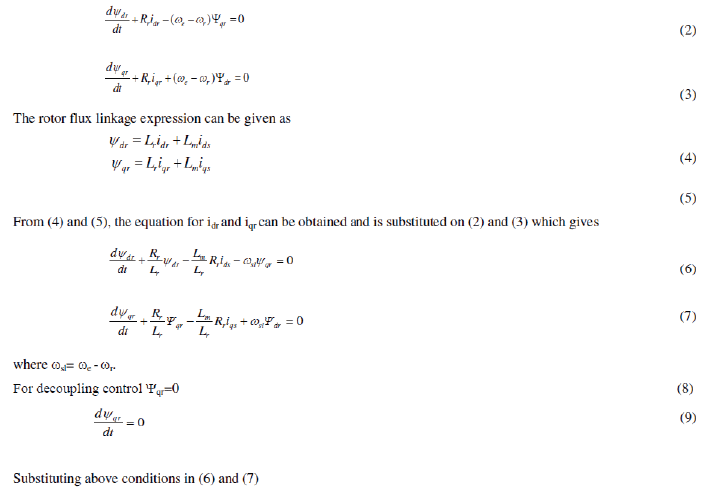
| The rotor circuit equation can be written as |
 |
 (10) (10) |
 |
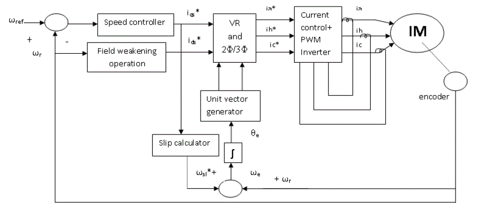
| Fig. 2 shows the block diagram of an indirect vector controlled induction motor drive.In this unit vectors are generated from the slip speed, ωsl and rotor speed ,ωr. |
CONTROL PRINCIPLE
|
| In this paper, for speed control of an indirect vector controlled induction motor both conventional (PI) and artificial intelligent (FLC) control methods are used. |
| A. PI controller |
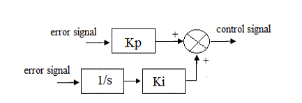
| First approach uses a conventional PI controller. The conventional PI controller has been frequently used for control action. By means of poles placement, it is quite easy to tune the controller. The structure of PI controller is shown in Fig. 2. |
| B. Fuzzy Logic Controller (FLC) |
| Second approach uses a fuzzy logic controller. Fig. 3 shows the fuzzy logic structure in which K1, K2 and K3 are known as scaling factors which is very important in fuzzy logic controller. Selection of scaling factors is made based on the knowledge about the process to be controlled. Sometimes it is set through trial and error to achieve the best possible control performance. |
DESIGN OF FUZZY LOGIC CONTROLLER
|
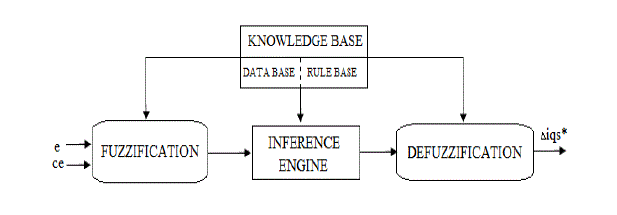
| Fuzzy logic controller utilizes the rules obtained from human expertise or input-output mapping of controlled plant. The inputs to the FLC are the linguistic variables of speed error (e) and change in speed error (ce) and the output is torque component of stator current. Fig. 4 shows the internal structure of a FLC. It consists of four blocks: fuzzication, knowledge base, inference engine and defuzzification. |
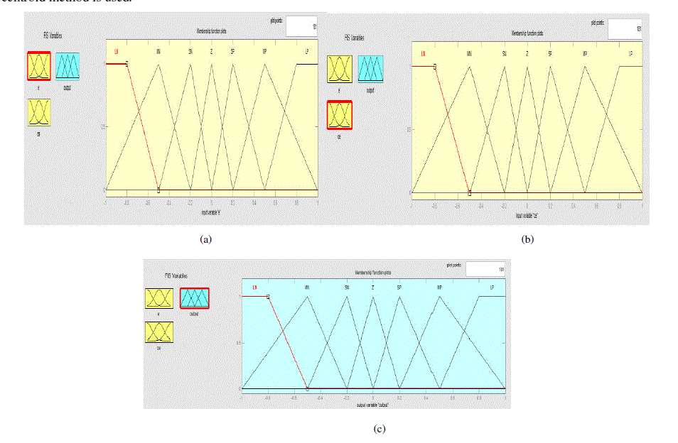
| The crisp variables of control inputs are converted into fuzzy variables by the fuzzification module. A fuzzy variable has values, which are defined by gradually varying membership function. Membership function can have different shape and triangular, trapezoidal and gaussian shaped membership function is most commonly used. The proposed controller uses following linguistic labels LN, MN, SN, Z, SP, MP, and LP. Each of the inputs and outputs contain membership function with all these 7 linguistic. |
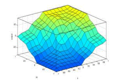
| A fuzzy control essentially embeds the experience and intuition of a human operator. The data base and the rule form the knowledge base with which the inference relation is obtained. Knowledge base involves defining the rules represented as IF-THEN rules statement which governs the relationship between input and output variables in terms of membership function. The ‘IF’-side of the rule is called the antecedent (conditionΨ and the ‘THEN’-side is called the consequent (conclusion).In this stage, the inference engine processes the input variables and executes 49 rules represented in rule table below. The first rule can be stated as if ‘e’ is LN and ‘ce’ is LN then the control output is LN. Here Mamdani’s algorithm is used. |
| The mathematical procedure of converting fuzzy values back to crisp values is known as defuzzification. Some of the defuzzification methods are centroid method or centre of gravity method, centre of sums and mean of maxima. Here centroid method is used. |
SIMULATION AND RESULT ANALYSIS
|
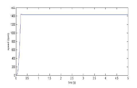
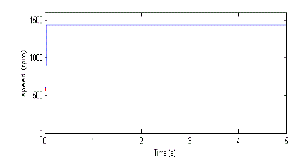
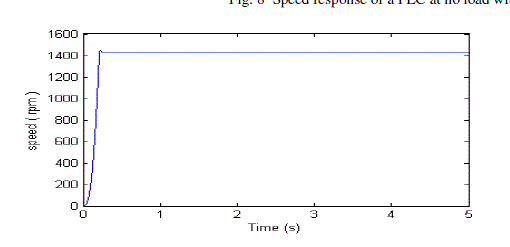
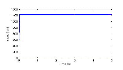
| The conventional PI and fuzzy logic controller based IFOC technique were developed for a 1.1kW IMD. The parameter of the machine is given in TABLE II. Fig. 7 and Fig. 8 shows the speed response of a PI and fuzzy logic controller respectively at no load with a speed reference of 1430 rpm.PI controller results a response with maximum overshoot of 1.04% where as the fuzzy controller results zero overshoot. The settling time for fuzzy controller is less as compared to that of PI controller. The settling time of a PI controller based scheme is 0.4 s and that of FLC is 0.08 s.Now a load is applied at 3 s. and response are observed. When loaded at 3 sec FLC recovers the speed faster than PI controller. |
| From Fig.11 (a) and (b),it is clear that in case of fuzzy controller the error settles faster than that of PI controller. The operation is also extended to field weakening region and Fig.12 (a) and (b) shows the speed response and flux of the system explaining the field weakening operation. Up to base speed, the flux is constant and when the speed crosses the base speed,flux decreases. |
CONCLUSION
|
| The concept of Fuzzy logic has been described in this paper and the rotor-flux oriented Indirect Vector Controlled Induction Motor Drive using PI and Fuzzy Logic Controller as speed controller is simulated and their performances were compared. The simulation results obtained have confirmed that the intelligent controller-FLC realizes a good dynamic behaviour of the motor with a faster settling time and zero overshoot than conventional PI controller. Also the operation was extended to above base speed and results were satisfactory. |
Tables at a glance
|
|
|
Figures at a glance
|
 |
 |
 |
 |
 |
| Figure 1 |
Figure 2 |
Figure 3 |
Figure 4 |
Figure 5 |
 |
 |
 |
 |
 |
| Figure 6 |
Figure 7 |
Figure 8 |
Figure 9 |
Figure 10 |
 |
 |
| Figure 11 |
Figure 12 |
|
References
|
- J.B.Gupta.Theory and Performance of Electrical Machines, 14th edition, S.K.Kataria and sons.
- GopalK.Dubey. Fundamentals of Electrical Drives, 2nd edition, Narosa Publishing House.
- Bimal.K.Bose 2002 .Modern Power Electronics and AC Drives, Prentice-Hall.
- KhalafSalloumGaeid , Hew Wooi Ping, HaiderA.F.Mohamed “Indirect Vector Control of a Variable Frequency Induction Motor Drive (VCIMDΨ,”Proc.ICICI-BME 2009.
- M. N. Uddin, T. S. Radwan and M. A. Rahman “Performances of Fuzzy-Logic-Based Indirect Vector Control for Induction Motor Drive,” IEEE Trans.on Industry Applications, Vol. 38, No. 5, pp. 1219-1225, September/October, 2002.
- Vinod Kumar, R. R. Joshi, “Hybrid Controller based Intelligent Speed Control of Induction Motor”, Journal of Theoretical and Applied.
- Rohit Gupta, Ruchika, “ Intelligent Induction Motor Drive”, International Journal of Computer Applications , Volume 50– No.22, July 2012.
- Peter Vas, Artificial Intelligence-Based Electrical Machines and Drives. Gi-Won Chang, Gerardo Espinosa-Pérez, Eduardo Mendes, and Romeo Ortega,“Tuning rule for the PI gains of field-oriented control of Inductionmotors ,” IEEE Trans..Industrial Electronics. vol. 47, No.3,June 2000.
|