Keywords
|
| VDigital signal processing (DSP), faithful rounding, finite impulse response (FIR) filter, truncated multipliers, VLSI design |
INTRODUCTION
|
| FINITE impulse response (FIR) digital filter is one of the fundamental components in many digital signal processing (DSP) and communication systems. It is also widely used in many portable applications with limited area and power budget. A general FIR filter of order M can be expressed as |
 |
| In case of linear phase, the coefficients are either symmetric or anti-symmetric with ai= aM-i or ai= −aM-i . |
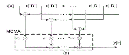
| There are two basic FIR structures, direct form and transposed form, the multiple constant multiplication (MCM)/accumulation (MCMA) module performs the concurrent multiplications of individual delayed signals and respective filter coefficients, followed by accumulation of all the products. Thus, the operands of the multipliers in MCMA are delayed input signals x[n − i] and coefficients ai. |
| The operands of the multipliers in the MCM module are the current input signal x[n] and coefficients. The results of individual constant multiplications go through structure adders (SAs) and delay elements. In order to avoid costly multipliers, most prior hardware implementations of digital FIR filters can be divided into two categories: multiplier based and memory based. |
| Multiplier-based designs realize MCM with shift-and add operations and share the common sub operations using canonical signed digit (CSD) recoding and common sub-expression elimination (CSE) to minimize the adder cost of MCM. The more area savings are achieved by jointly considering the optimization of coefficient quantization and CSE. Most multiplier MCM-based FIR filter designs use the transposed structure to allow for cross-coefficient sharing and tend to be faster, particularly when the filter order is large. However, the area of delay elements is larger compared with that of the direct form due to the range expansion of the constant multiplications and the subsequent additions in the SAs. Blad and Gustafsson presented high-throughput (TP) FIR filter designs by pipelining the carry-save adder trees in the constant multiplications using integer linear programming to minimize the area cost of full adders (FAs), half adders (HAs), and registers (algorithmic and pipelined registers). |
| Memory-based FIR designs consist of two types of approaches: lookup table (LUT) methods and distributed arithmetic (DA) methods. The LUT-based design stores in ROMs odd multiples of the input signal to realize the constant multiplications in MCM. The DA-based approaches recursively accumulate the bit-level partial results for the inner product computation in FIR filtering. |
| In this brief, we present low-cost implementations of FIR filters based on the direct structure with Booth multipliers. The MCMA module is realized by accumulating all the partial products (PPs) where unnecessary PP bits (PPBs) are removed without affecting the final precision of the outputs. The bit widths of all the filter coefficients are minimized using non-uniform quantization with unequal word lengths in order to reduce the hardware cost while still satisfying the specification of the frequency response. |
COEFFICIENT QUANTIZATION AND OPTIMIZATION
|
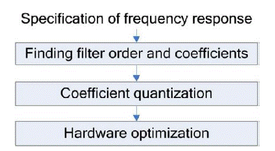
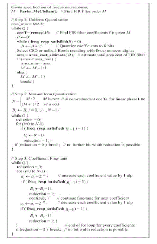
| A generic flow of FIR filter design and implementation can be divided into three stages: finding filter order and coefficients, coefficient quantization, and hardware optimization, in the first stage, the filter order and the corresponding coefficients of infinite precision are determined to satisfy the specification of the frequency response. Then, the coefficients are quantized to finite bit accuracy. Finally, various optimization approaches such as CSE are used to minimize the area cost of hardware implementations. Most prior FIR filter implementations focus on the hardware optimization stage. |
| In this brief, we adopt the direct FIR structure with MCMA because the area cost of the flip-flops in the delay elements is smaller compared with that of the transposed form. Furthermore, we jointly consider the three design stages in order to achieve more efficient hardware design with faithfully rounded output signals. |
| After coefficient quantization, we perform recoding to minimize the number of nonzero digits. In this brief, we consider CSD recoding with digit set of {0, 1, −1} and radix-4 modified Booth recoding with digit set of {0, 1,−1, 2,−2} and select the one that results in smaller area cost. |
| While most FIR filter designs use minimum filter order, we observe that it is possible to minimize the total area by slightly increasing the filter order. Therefore, the total area of the FIR filter is estimated using the subroutine area, cost and estimate (). Indeed, the total number of PPBs in the MCMA is directly proportional to the number of FA cells required in the PPB compression because a FA reduces one PPB. |
| After Step 1 of uniform quantization and filter order optimization, the non-uniform quantization in Step 2 gradually reduces the bit width of each coefficient until the frequency response is no longer satisfied. |
| Finally, we fine-tune the non-uniformly quantized coefficients by adding or subtracting the weighting of LSB of each coefficient and check if further bit width reduction is possible. We can find the filter order M and the non-uniformly quantized coefficients that lead to minimized area cost in the FIR filter implementation. |
BOOTH MULTIPLIER
|
| It is a powerful algorithm for signed-number multiplication, which treats both positive and negative numbers uniformly. |
| For the standard add-shift operation, each multiplier bit generates one multiple of the multiplicand to be added to the partial product. If the multiplier is very large, then a large number of multiplicands have to be added. In this case the delay of multiplier is determined mainly by the number of additions to be performed. If there is a way to reduce the number of the additions, the performance will get better. |
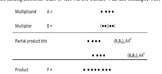
| Booth algorithm is a method that will reduce the number of multiplicand multiples. For a given range of numbers to be represented, a higher representation radix leads to fewer digits. Since a k-bit binary number can be interpreted as K/2-digit radix-4 number, a K/3-digit radix-8 number, and so on, it can deal with more than one bit of the multiplier in each cycle by using high radix multiplication. This is shown for Radix-4 in the example below. |
| As shown in the figure above, if multiplication is done in radix 4, in each step, the partial product term (Bi+1Bi)2 A needs to be formed and added to the cumulative partial product. Whereas in radix-2 multiplication, each row of dots in the partial products matrix represents 0 or a shifted version of A must be included and added. |
| Table 1below is used to convert a binary number to radix-4 number. Initially, a “0” is placed to the right most bit of the multiplier. Then 3 bits of the multiplicand is recoded according to table below or according to the following equation: |
| Zi = -2xi+1 + xi + xi-1 |
| Example: |
| Multiplier is equal to 0 1 0 1 1 10 0 added |
| the 3 digits are selected at a time with overlapping left most bit as follows: |
| For example, an unsigned number can be converted into a signed-digit number radix 4: |
| (10 01 11 01 10 10 11 10)2 = (–2 2 –1 2 –1 –1 0 –2)4 |
| The Multiplier bit-pair recoding is shown in Table .2 |
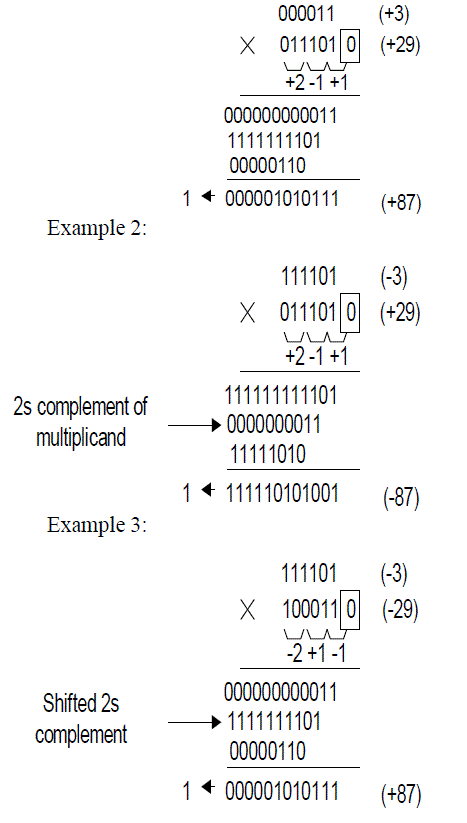
| Here –2*multiplicand is actually the 2s complement of the multiplicand with an equivalent left shift of one bit position. Also, +2 *multiplicand is the multiplicand shifted left one bit position which is equivalent to multiplying by 2. |
| To enter ± 2*multiplicand into the adder, an (n+1)-bit adder is required. In this case, the multiplicand is offset one bit to the left to enter into the adder while for the low-order multiplicand position a 0 is added. Each time the partial product is shifted two bit positions to the right and the sign is extended to the left. |
| During each add-shift cycle, different versions of the multiplicand are added to the new partial product depends on the equation derived from the bit-pair recoding table above. |
| Let’s see some examples: |
 |
EXPERIMENTAL RESULTS
|
 |
 |
 |
 |
 |
CONCLUSION
|
| This brief has presented low-cost FIR filter designs by jointly considering the optimization of coefficient bit width and hardware resources in implementations. In this method a Booth multiplier is implemented. By using Booth multiplier to multiply the signed numbers also. Although most prior designs are based on the transposed form, gives information about the direct FIR structure with booth multiplier leads to the smallest area cost and power consumption. |
Tables at a glance
|
 |
 |
| Table 1 |
Table 2 |
|
Figures at a glance
|
 |
 |
 |
 |
 |
| Figure 1 |
Figure 2 |
Figure 3 |
Figure 4 |
Figure 5 |
|
References
|
- P. K. Meher, “New approach to look-up-table design and memory-based realization of FIR digital filter,” IEEE Trans. Circuits Syst. I, Reg. Papers, vol. 57, no. 3, pp.592–603, Mar. 2010.
- P. K. Meher, S. Candrasekaran, and A. Amira, “FPGA realization of FIR filters by efficient and flexible systolization using distributed arithmetic,” IEEE Trans. SignalProcess., vol. 56, no. 7, pp. 3009–3017, Jul. 2008.
- F. Xu, C. H. Chang, and C. C. Jong, “Contention resolution—A new approach to versatile subexpressions sharing in multiple constant multiplications,” IEEE Trans.Circuits Syst. I, Reg. Papers, vol. 55, no. 2, pp. 559–571, Mar. 2008.
- F. Xu, C. H. Chang, and C. C. Jong, “Contention resolution algorithms for common subexpression elimination in digital filter design,” IEEE Trans. Circuits Syst. II,Exp. Briefs, vol. 52, no. 10, pp. 695–700, Oct. 2005.
- I.-C. Park and H.-J. Kang, “Digital filter synthesis based on an algorithm to generate all minimal signed digit representations,” IEEE Trans. Comput.-Aided DesignIntegr. Circuits Syst., vol. 21, no. 12, pp. 1525–1529, Dec. 2002.
- Blad and O. Gustafsson, “Integer linear programming-based bit-level optimization for high-speed FIR filter architecture,” Circuits Syst. Signal Process., vol. 29, no.1, pp. 81–101, Feb. 2010.
- F. Xu, C. H. Chang, and C. C. Jong, “Design of low-complexity FIR filters based on signed-powers-of-two coefficients with reusable common subexpressions,” IEEETrans. Comput.-Aided Design Integr. Circuits Syst., vol. 26, no. 10, pp. 1898–1907, Oct. 2007.
- Y. J. Yu and Y. C. Lim, “Design of linear phase FIR filters in subexpression space using mixed integer linear programming,” IEEE Trans. Circuits Syst. I, Reg.Papers, vol. 54, no. 10, pp. 2330–2338, Oct. 2007.
- K. C. Bickerstaff, M. Schulte, and E. E. Swartzlander, Jr., “Reduced area multipliers,” in Proc. Int. Conf. Appl.-Specific Array Processors, 1993,pp. 478–489.
- R. Huang, C.-H. H. Chang, M. Faust, N. Lotze, and Y. Manoli, “Signextension avoidance and word-length optimization by positive-offset representation for FIRfilter design,” IEEE Trans. Circuits Syst. II, Exp. Briefs, vol. 58, no. 12, pp. 916–920, Oct. 2011.
- M. M. Peiro, E. I. Boemo, and L. Wanhammar, “Design of high-speed multiplierless filters using a nonrecursive signed common subexpression algorithm,” IEEETrans. Circuits Syst. II, Analog Digit. Signal Process., vol. 49, no. 3, pp. 196–203, Mar. 2002.
- C.-H. Chang, J. Chen, and A. P. Vinod, “Information theoretic approach to complexity reduction of FIR filter design,” IEEE Trans. Circuits Syst. I, Reg. Papers, vol.55, no. 8, pp. 2310–2321, Sep. 2008.
- S. Hwang, G. Han, S. Kang, and J.-S. Kim, “New distributed arithmetic algorithm for low-power FIR filter implementation,” IEEE Signal Process. Lett., vol. 11, no.5, pp. 463–466, May 2004.
- H.-J. Ko and S.-F. Hsiao, “Design and application of faithfully rounded and truncated multipliers with combined deletion, reduction, truncation, and rounding,” IEEETrans. Circuits Syst. II, Exp. Briefs, vol. 58, no. 5, pp. 304–308, May 2011.
- H. Samueli, “An improved search algorithm for the design of multiplierless FIR filters with powers-of-two coefficient,” IEEE Trans. Circuits Syst., vol. 36, no. 7, pp.1044–1047, Jul. 1989.
- Y. C. Lin and S. Parker, “Discrete coefficient FIR digital filter design based upon an LMS criteria,” IEEE Trans. Circuits Syst., vol. 30, no. 10, pp. 723–739, Oct.1983.
- U. SudhaRani,S.P. Suresh Naik “LUT based FIR Filter Design & implementation on FPGA using Faithfully Rounded Truncated Multiple Constant Multiplication/Accumulation” published in International Journal of Engineering Research Volume No.3 Issue No: Special 2,
|