Keywords
|
| Dual-Tree Complex Wavelet Transform, Nonlocal Means, Bilinear Interpolator ,Resolution Enhancement. |
INTRODUCTION
|
| Resolution is the most common limiting factor for the utilization of remote sensing data satellite imaging, etc. Spectral and spatial resolutions of satellite images are related with each other. Therefore, spectral, as well s spatial, Resolution Enhancement (RE) is desirable. Inorder to gain RE, interpolation has been widely used. Commonly used Interpolation techniques are based on nearest neighbors like nearest neighbor, bilinear, bicubic, and Lanczos. Bilinear Interpolator is an accurate way of interpolating an image than with the nearest neighbor method but also requires more processing time. |
| The non-wavelet based RE schemes suffer from the drawback of losing high-frequency contents which results in blurring. RE in the wavelet domain has many algorithms such as Discrete Wavelet Transform (DWT), Stationary Wavelet Transform (SWT), and Dual-Tree Complex Wavelet Transform (DT-CWT) [11].Most recently, an RE scheme was proposed using DT-CWT and Lancoz interpolations, and results were compared with the conventional schemes i.e., nearest neighbour and bicubic interpolations and wavelet zero padding [11] . A scheme based on DWT and bicubic interpolation was proposed, and results were compared with the conventional schemes and the state-of-art schemes[3].DWT is shift variant, which causes artifacts in the RE image, and has a lack of directionality; however, DTCWT is almost shift and rotation invariant . |
| As resolution is an important feature in satellite imaging but it directly affect the performance of the system where these images are used as input The main loss of a resolution enhanced image is its high-frequency components, which is due to the smoothing caused by interpolation. Hence, in order to increase the quality of the enhanced image, it is essential to preserve the edges. And the wavelet-transform-based RE scheme generates artifacts because of the decomposition of high frequency sub-bands using DWT shift-variant property[3]. Moreover, edges are not detected because of losing high frequency sub-bands |
RELATED WORK
|
| In an industrial point of view, there are different existing systems that are to be considered while developing a resolution enhanced image. Some of them are discussed with the drawbacks of the same.The Dual-Tree Complex Wavelet Transform (DT- WT) is an enhancement of the conventional Discrete Wavelet Transform (DWT) that is considered as a signal processing tool. The transform is to circumvent the shift-variance problem of the decimated DWT, that involves two parallel DWT channels with the corresponding wavelets forming approximate Hilbert transform pairs. |
| The DT- WT exhibit better shift-invariance than the conventional discrete wavelet transform. Here, an amplitudephase representation [9] of the DT- WT is used, which offers a direct explanation for the improvement in the shiftinvariance. The representation is based on the shifting action of the group of fractional Hilbert Transform (fHT) operators, which extends the notion of arbitrary phase-shifts from sinusoids to finite-energy signals. The disadvantage is that DT-CWT is almost shift and rotation invariant. And also the output RE image, has a lack of directionality. |
| In this paper, a satellite image resolution enhancement technique based on the interpolation of the high-frequency sub bands obtained by Discrete Wavelet Transform (DWT) [3] and the input image. The DWT is used to decompose the input image into different sub bands. Then, the high-frequency sub band images and the input low-resolution image have been interpolated. Then these images are combined to generate a new resolution-enhanced image by using inverse DWT. In order to achieve a sharper image, an intermediate stage for interpolating the high-frequency sub bands has been used. This technique has been tested on satellite benchmark images. The quantitative (peak signal-to-noise ratio and root mean square error) and visual results show the superiority of this technique over the conventional and state-ofart image resolution enhancement techniques. The disadvantage is that losing of high-frequency contents and DWTbased RE schemes generate artifacts. |
| Discrete Wavelet Transform (DWT) [4] decomposes an image into different sub-band images, namely Low-Low (LL), Low-High (LH), High-Low (HL), and High-High (HH).Here, DWT is used to decompose a low resolution image into different sub bands. Then the high frequency sub band images have been interpolated using bicubic interpolation. The high frequency sub bands obtained by the decomposition of the input image are being incremented into the interpolated high frequency sub bands in order to correct the estimated coefficients. In parallel, the input image is also interpolated separately. Then the corrected interpolated high frequency sub-bands and interpolated input image are combined by using Inverse DWT (IDWT) to achieve a high resolution output image. This technique has been compared with conventional and state-of-art image resolution enhancement techniques. According to the quantitative and qualitative experimental results, this technique helps to attain resolution enhanced image. The disadvantage is that this method lags reduction of aliasing, sharpness and ringing. |
PROPOSED SYSTEM
|
| Resolution Enhancement (RE) schemes suffer from the drawback of losing high frequency contents. The Discrete Wavelet-Transform-based (DWT) RE scheme generates artifacts. Therefore a Multi level DT-CWT and Non Local- Means based RE technique is proposed, using the multilevel DT-CWT, Bilinear interpolation, and NLM. Multi level DT-CWT is nearly shift invariant and directional selective. Moreover, Multilevel DT-CWT preserved the usual properties of perfect reconstruction with well-balanced frequency responses. |
| A Multilevel Dual Tree Complex Wavelet Transform |
| Satellite image quality may get disturbed while capturing, processing and storing the image.In images, noise suppression is a particularly a delicate task. The wavelet transform provides a multi resolution representation using a set of analyzing functions that are dilations and translations of a few functions (wavelets). |
| Multilevel dual tree complex wavelet transform when compare to dual tree complex wavelet transform which has extra added one filters .The filter used helps to construct image in one form into another form and the frequency variation is involved in each tree in the existing system .In this proposed method, added much filters but easily reconstruct the data easily. And for each of the directions, one of the wavelets can be interpreted as the real part and the other can be interpreted as the imaginary part. This transform is implemented by applying four MDTCWTs in parallel with distinct filter sets for the rows and columns. In this technique ,4 filters are combined to perform one image denoising process . |
| The Multilevel DT-CWT decomposes the low resolution input image to obtain the high frequency sub bands. It more selectively discriminates features of various Orientations. The critically decimated multilevel DT CWT outputs has three orientation selective sub bands per level conveying image features oriented at the angles of 90° , ± 45° , and 0° and produces six directional sub bands per level to reveal the details of an image in ±15° ,± 45° and ± 75° directions with 4:1 redundancy |
| The implementation of Multi level DT CWT consists of two steps. Firstly, an input image is decomposed to to obtain two separable branches, branch a and branch b, whose filters are designed to meet the Hilbert pair requirement .Then six high-pass sub bands are generated at each level. |
 |
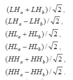
| Secondly, every two corresponding sub bands that have the same pass bands are linearly combined by either averaging or differencing. And the sub bands at each level are obtained as |
 |
| The six wavelets are defined by oriented, as shown in above .Because the sum/difference operation is orthonormal ,this constitutes a perfect reconstruction of wavelet transform. The imaginary part of Multilevel DT-CWT has function similar to the real part . |
| B Bilinear Interpolation |
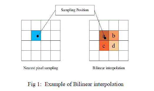
| Bilinear Interpolation is used for resizing an image. During this stage, the high frequency sub bands, which is the output of multilevel DT CWT is interpolated with the low resolution input image .It is a non adaptive algorithm for increasing or decreasing the number of pixels in a digital image. This is a more accurate way of interpolating an image than with the nearest neighbor method but also requires more processing time by comparing all surrounding pixels in a 2x2 area. |
| C Non Local Means Filter |
| C.1 Non-Local Means Algorithm |
| C.2 Non-Local Means Method |
| Each pixel p of the denoised image by Non Local Means is computed with the following formula: |
 |
Where V is the noisy image, and weights w (p,q) meet the following conditions  |
| And |
 |
| Each pixel p is a weighted average of all the pixels in the image. The weights are based on the similarity between the neighborhoods of pixels p and q [1, 2].To compute the similarity between pixels, a neighborhood must be defined. Let Ni be the square neighborhood centered about pixel i with a user- defined radius Rsim. |
| To compute the similarity between two neighborhoods take the weighted sum of squares difference between the two neighbourhoods or as a formula |
 |
| F is the neighborhood filter applied to the squared difference of the neighborhoods. The weights can then be computed as: |
 |
| Z (p) is the normalizing constant defined as |
 |
| h is the weight-decay control parameter |
| And the weights of F are computed by the following formula: |
 |
| Where m is the distance the weight is from the center of the filter. The filter gives more weight to pixels near the center of the neighborhood, and less weight to pixels near the edge of the neighborhood. The center weight of F has the same weight as the pixels with a distance of one. Despite the filter's unique shape, the weights of filter F do sum up to one. |
| Equation (1) from above does have a special case when q = p. This is because the weight w (p,p) can be much greater than the weights from every other pixel in the image. |
| D Inverse Dual Tree Wavelet Transforms |
| The inverse DT-CWT is applied to the the filtered sub bands that is free of artifacts along with the interpolated LR input image to reconstruct the RE image. The inverse of the DT CWT can be performed as simple as the forward transform. To invert the transform, the real part and the imaginary part are each inverted and the two real signals are obtained from the inverse of each of the two real DWTs. From the average of these two real signals , the final output is obtained. |
| The inverse of the DT CWT is self-inverting in the terminology of the Dual-Tree Wavelet Transform. The inverse DT CWT defined in keeps the real and imaginary parts of the complex wavelet coefficients separate, and if the two real DWTs are orthonormal transforms, then the DT CWT is satisfied. For a real N-point signal, the form in yields 2N complex coefficients, but N of these coefficients is the complex conjugates of the other N coefficients. For a general complex, N-point signal, the form in yields 2N general complex coefficients. For both real and complex input signals, the DT CWT is two times expansive. |
CONCLUSION
|
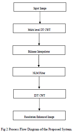
| A technique based on wavelet-domain approach using multi level Dual-Tree Complex Wavelet Transforms (DTCWT) and Non Local Means (NLM) for decomposing the satellite images. Input image is decomposed by multi level DT-CWT to get more no of high-frequency sub-bands when compared to single stage. The high-frequency sub bands and the Low-Resolution (LR) input image are interpolated using the Bilinear interpolator. The high frequency sub bands generate artifacts and are removed using Non Local Means Filter.Then the filtered high-frequency sub-bands and the LR input image are combined using inverse DT-CWT to obtain a super resolved high resolution image. |
Figures at a glance
|
 |
 |
| Figure 1 |
Figure 2 |
|
References
|
- Atkins C.B, C. A. Bouman, and J. P. Allebach, “Optimal image scaling Using pixel classification,” in Proc. Int. Conf. Image Process., Oct.7–10, 2001, pp. 864–867.
- Buades.A, B. Coll, and J. M. Morel, “A review of image denoising algorithms, with a new one,” Multisc. Model. Simul., vol. 4, no. 2, pp.490– 530, 2005.
- Demirel.H, and G. Anbarjafari, “Discrete wavelet transform-based satellite image resolution enhancement,” IEEE Trans. Geosci. RemoteSens., vol. 49, no. 6, pp. 1997–2004, Jun. 2011
- Demirel.H, and G. Anbarjafari, “Image resolution enhancement by using discrete and stationary wavelet decomposition,” IEEE Trans. ImageProcess., vol. 20, no. 5, pp. 1458–1460, May 2011.
- Demirel.H, and G. Anbarjafari, “Satellite image resolution enhancement using complex wavelet transform,” IEEE Geosci. Remote Sens.Lett., vol. 7, no. 1, pp. 123 126, Jan. 2010.
- Demirel.H and G. Anbarjafari, “Image super resolution based on interpolation of wavelet domain high frequency sub-bands and the spatialdomain input image,” ETRI J., vol. 32, no. 3, pp. 390–394, Jan. 2010.
- Glassner.A.S, K. Turkowski, and S. Gabriel, “Filters for common resampling tasks,” in Graphics Gems. New York: Academic, 1990, pp.147–165.
- Gambardella.A and M.Migliaccio, “On the super resolution of microwave Scanning radiometer measurements,” IEEE Geosci. Remote SensLett., vol. 5, no. 4, pp. 796–800, Oct. 2008.
- Kunal Narayan Chaudhury and Michael Unser “On the Shiftability of Dual-Tree Complex Wavelet Transforms” Vol. 58, No. 1, January 2010221
- Piao.Y, I. Shin, and H. W. Park, “Image resolution enhancement using inter-sub band correlation in wavelet domain,” in Proc. Int. Conf.Image Process., San Antonio, TX, 2007, pp. I-445–I-448.
- Selesnick.W, R. G. Baraniuk, and N. G. Kingsbur, “The dual-tree complex wavelet transform,” IEEE Signal Prcess. Mag., vol. 22, no. 6, pp.123–151, Nov. 2005.
- Tschumperle.D ,and R. Deriche, “Vector-valued image regularization with PDE’s: A common framework for different applications,”IEEETrans.Pattern Anal. Mach. Intell., vol. 27, no. 4, pp. 506–517, Apr. 2005.
- Wang.Z and A. C. Bovik, “A universal image quality index,” IEEE Signal Process. Lett., vol. 9, no. 3, pp. 81–84, Mar. 2002.
- Xin Li, “New Results of Phase Shifting in the Wavelet Space”, IEEE Signal Processing Letters, Vol.10, No.7, July 2003
|