Keywords
|
| Include Static Synchronous compensator, Voltage source converter, Fast Fourier Transform, Phase Shifting Transformers, Total harmonics Distortion |
INTRODUCTION
|
| In recent years, major transformations have been introduced into the structure of electrical power utilities to improve efficiency in the operation of the power system networks by deregulating the industries and opening it to their private competitors .Voltage stability and control are increasingly becoming a limiting factor in the planning and operation of some power systems. This results into the adaptation to a new set of rules dictated by deregulated markets in generation, transmission and distribution systems. In particular for the transmission sector of power utilities, a variety of considerations constrains the construction of new transmission lines. |
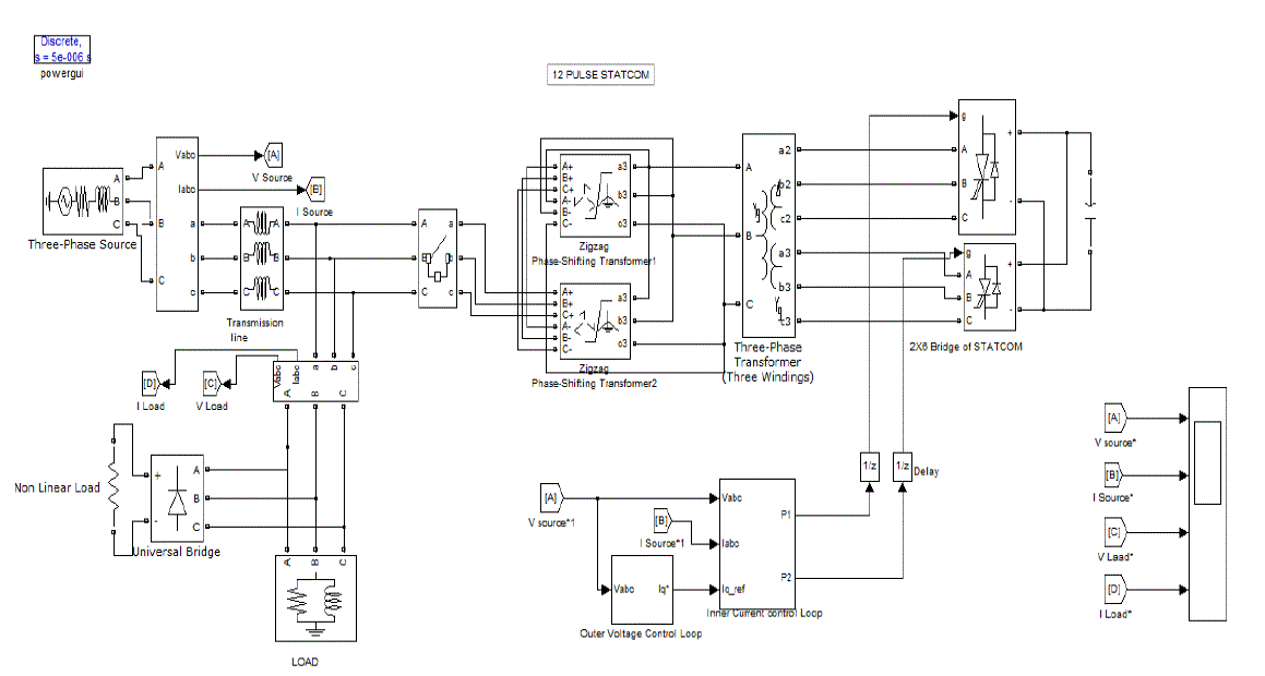
| The technical and Economical constrains can be satisfied with the application of FACTS devices. The availability of semiconductor devices such as thyristors and gate turn-off thyristors (GTO) in suitable ratings makes such applications feasible. The advent of Flexible AC Transmission Systems (FACTS) is giving rise to a new family of power electronic equipment emerging for controlling and optimizing the performance of power system, e.g. STATCOM, SSSC and UPFC.STATCOM is a shunt compensation device. In the STATCOM stated above two elementary 6 pulse GTO-VSC are employed with a Capacitor as a Voltage source. TO are fired with the fundamental frequency switching methods. PI Controller are used in Voltage and current controller loop. The voltage control loop is used for producing and current control loop, are adopted in d-q rotating frame reference for controlling α angle for generating pulses. The Interfacing Magnetics provided consist in two stages. One is Converting transformer (Y-YΔ) and second is Phase shifting transformers +15 and -15 degrees of phase shift. |
| The 2 Level STATCOM generally produce 12n+1 harmonics, specially 5th, 7th, 11th and 13th harmonics and a Non-Linear Load i.e. Universal bridge in parallel to the resistance, is also provided that inject additional harmonics in Load, depending upon the value of the resistance provided. The proposed 12 pulse 2 level STATCOM is simulated to reduce the harmonics at source up to satisfactory value. |
PRINCIPLE OF STATCOM
|
| The STATCOM is basically a DC-AC voltage source converter with an energy storage unit, usually a DC capacitor. It operates as a controlled Synchronous Voltage Source (SVS) connected to the line through a coupling transformer. The main objective of STATCOM is to control reactive current by generation and absorption of controllable reactive power. The controlled output voltage is maintained in phase with the line voltage, and can be controlled to draw either capacitive or inductive current from the line in a similar manner of a synchronous condenser, but much more rapidly. The essential components in a VSC based STATCOM are GTO-VSC bridge(s), DC capacitor(C) working as an energy storage device, inter-facing magnetic forming the electrical coupling between the VSC bridge circuits, AC mains system and controllers generating gating signals. when the STATCOM voltage increases then the system voltage (V> )then it supplies the reactive current to the system that mode is called capacitive mode and when system voltage is more then the STATCOM voltage( >V) then it works in the inductive mode. The STATCOM is said to be floating when both voltages are equal to each other. Ideally STATCOM output voltage should be in phase with the system voltage but a small phase difference is kept to meet the losses of the voltage source converters. |
SIMULATION MODEL
|
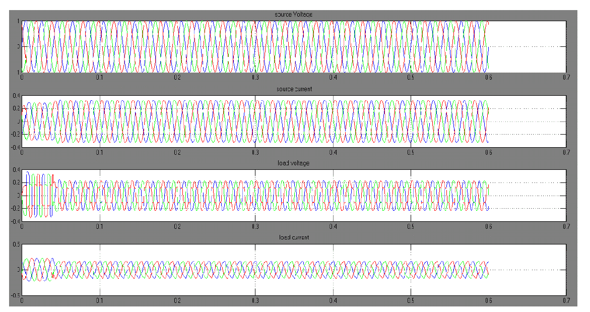
| The Simulation model of 12 pulse 2 level STATCOM with the Three phase Voltage source 132KV and having the short circuit capacity of 3000MVA is shown in Fig.1. Non-Linear load is kept at 50MW and the additional load is provided with the parallel load. The STATCOM is switched on at 0.04 sec, while load was applied from starting. |
| The results are taken on 50MW at 0.8 pf and 100MW at0.8pf. with and without considering the saturation of the phase shifting transformers. The resistance of the bridges is kept at 0.1Ω.In the 12 pulse STATCOM 5th, 7th, 11th and 13th harmonics are dominating and considering the switching operations in the power system addition of 50 MW Non-linear load will increase these harmonics so interfacing magnetic used in two steps for eliminating the harmonics. Converting transformers used for eliminating the 5th and 7th harmonics and Phase shifting transformers (PST’s) are there for eliminating the 11th,13th harmonics. |
SIMULATION RESULTS
|
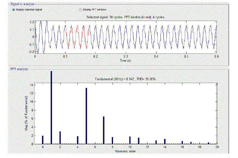
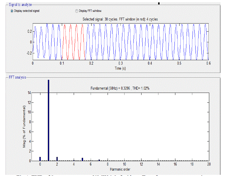
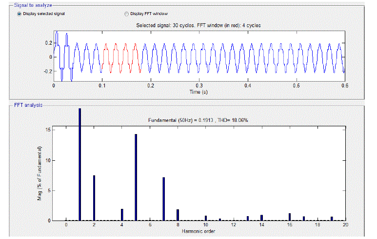
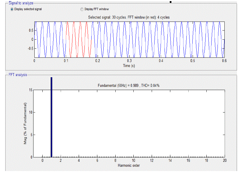
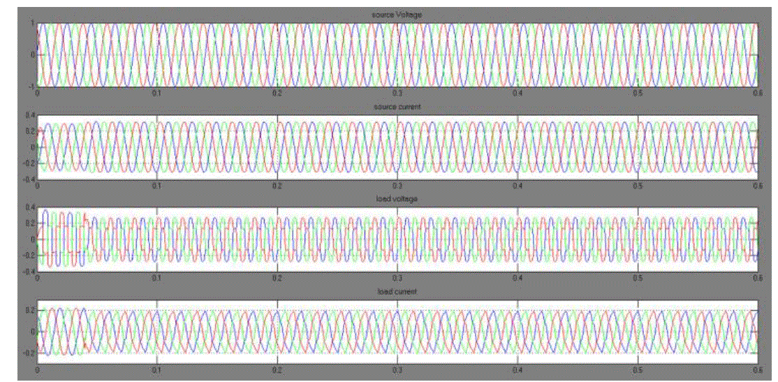
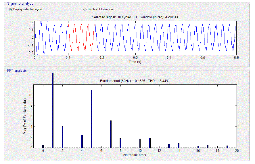
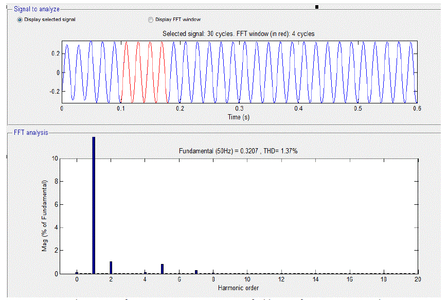
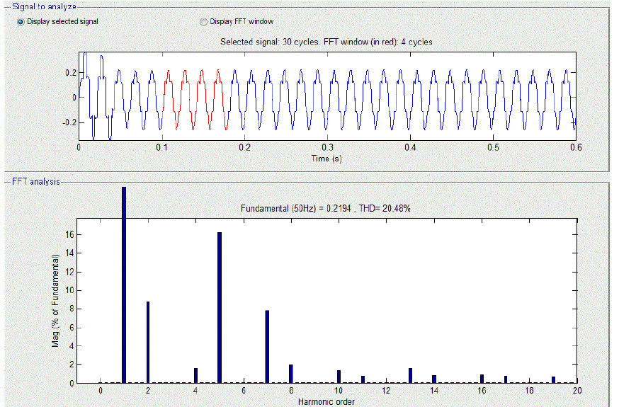
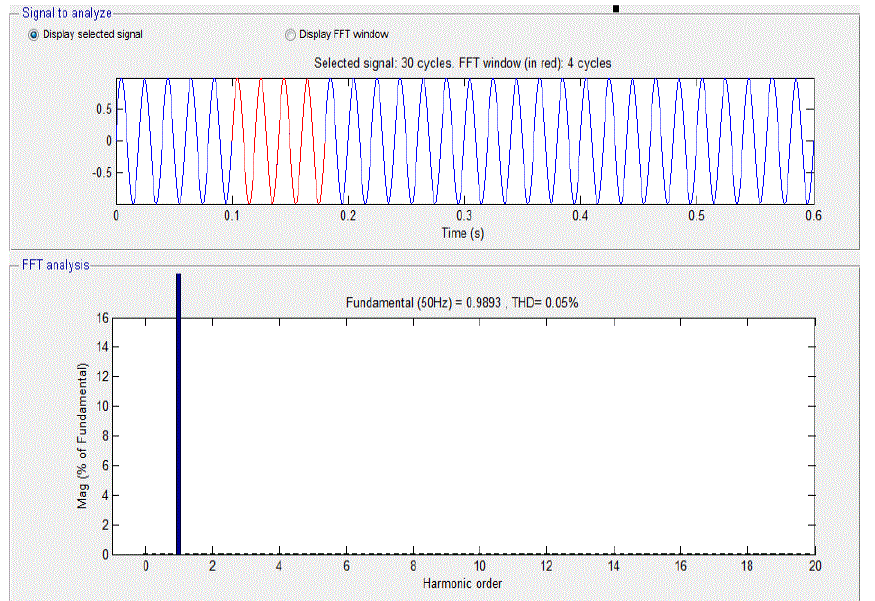
| In the Model shown above load is simulated from starting (t=0). The STATCOM comes into operation at time t=0.04 sec. The harmonics analysis is done in FFT tool of MATLAB The simulated load is of two types, One is Parallel load and other is Non- Linear Load which is kept at 50MW fixed.The waveform of Voltages and Currents are obtained at 50MW at 0.8pf and 100MW at 0.8pf. The waveform at different loads are obtained with & without considering the Transformers core saturation. The waveform obtained are analyzed for Harmonics into the FFT tool of MATLAB and after applying the STATCOM into the system their occur considerable decrease in the harmonics(5th,7th,11th and13th) at the source side as discussed above. The simulation results of source voltage, load voltage, source current, load current and their respective THDs are depicted in Figs.2 to 11. |
| As the results shows the Harmonics in the Current are reduced from 15.50% to 1.02% |
| The above results shows Harmonics are successfully reduced in the Voltage from 18.06% to 0.04% also. |
| As the results shows the Harmonics in the Current are reduced from 13.44% to 1.37% |
| The Results shows that Voltage Harmonics reduced from 20.48% to 0.05% |
CONCLUSION
|
| The proposed STATCOM model of 12 pulse 2 Level topology simulated at 132kV, +100MVAr STATCOM model to eliminate 5th, 7th, 11th, 13th and higher order of voltage harmonics produced by internal switching operation and External Non Linear load. The model is working properly and mitigating the particular Harmonics stated above. The results are satisfactory according to IEEE standards. |
Figures at a glance
|
 |
 |
 |
 |
 |
| Figure 1 |
Figure 2 |
Figure 3 |
Figure 4 |
Figure 5 |
 |
 |
 |
 |
 |
| Figure 6 |
Figure 7 |
Figure 8 |
Figure 9 |
Figure 10 |
 |
| Figure 11 |
|
References
|
- N. G. Hingorani and L. Gyugyi, “Understanding FACTS”Concepts and Tech. of Flexible AC transmission system” IEEE Press, 2000.
- FACTS Controllers in power Transmission and Distribution, K.R.Padiyar.
- B. Singh and R. Saha, “A New 24-Pulse STATCOM for Voltage Regulation,” International Conference on Power Electron. Drives and Energy Systems, 2006. PEDES '06, 12-15 Dec. 06, pp. 1-5..
- Luis Moron, Phoivos D. Ziogas and GezaJoos, ”A Solid State High Performance Reactive Power Compensator” IEEE Transactions on industry applications,Vol 29, no, 5, Sept 1993..
- IEEE Standard 519-1992, IEEE Recommended Practices and Requirements for Harmonic Control in Electrical Power Systems, IEEE Inc., New York, 1992
- Y.H. Song and A.T. Johns, “Flexible ac transmission systems (FACTS)”, The Institute of Electrical Engineers, London, 1999
|