Keywords
|
| circuit theory, deregulated system, loss allocation, orthogonal current projection, superposition theorem. |
INTRODUCTION
|
| In a balanced, stable and secured power system, generation should be equal to loss plus load in each and every second. Moreover ,reactive power is considered as an important support hand to the system operator. So loss of reactive power leads to loss of reliability of the system. Active power loss allocation has been focused mostly as main essential commodity in electricity market. As the generators and loads are connected within same network the change in one participant effects on others significantly resulting difficulty in determining the cost of each participants responsible for. So, it is very essential to develop a fair and transparent reactive power loss allocation method to avoid cross subsidies and to charge the participants as they deserve. In vertically integrated electricity industry, reactive power support is considered as a part of system operator’s activities and its cost which should be recovered is usually calculated based on approximate methods. |
| Many investigations have been carried out for appropriate pricing of reactive power [1–15]. Some of these methods utilize various search techniques such as genetic and ant colony algorithms for pricing [4], others have focused on formulating reactive power pricing [4-6]. Muchayi [6] have presented a survey on some of the reactive pricing algorithms. Dona and Paredes [7] have proposed a pricing technique based on minimization of the operation cost as well as the transmission losses using decoupled OPF. Cost allocation of reactive power using modified Y-bus matrix method has been reported by Chu and Chen [8]. Ro [9] has presented the reactive charging scheme composed of recovering capital cost and operational cost. Pricing of real and reactive power as bundled products in synchronous machine has been investigated in [10]. Rider and Paucar [11] have proposed a nonlinear reactive power pricing method. They have presented the total cost of reactive power production as an nonlinear model which is solved by modified predictor corrector interior-point method. Active and reactive pricing using interior point nonlinear optimization method has been demonstrated by Xie [12]. Chung et al. [13] have presented a method for cost-based reactive power pricing in which the cost of reactive power production by generators and capacitors are minimized. Also a methodology for calculation of cost of reactive power by generators, synchronous condenser and static reactive power sources has been reported by Deksnys and Staniulis [14]. Proportional sharing technique[15] provide a computationally efficient method for loss allocation. Here ,it is assumed that nodal inflows are shared proportionally among nodal outflows . |
| A very recent paper [16] presents a circuit based method for branch power flow decomposition and branch loss allocation based on concept of orthogonal projection .In paper [16] ,it is shown that the share of power injection at any bus on the power flow through any branch equals the ratio of its current projection component to the total branch current. In view of this analogy, paper[16] allocate loss to generators and loads proportionate to their current projection component .But this fact comes true as long as bus voltages remain constant .Where as bus voltages of a transmission network are ever changing ,due to variation of any loads or generations. |
| This paper also use the concept of orthogonal current projection component [16] where loss allocated to each branch solely depends on the orthogonal projection of current contributions. As per literature, one of the equivalence mode(CC) converts all generators and loads into current injection. But this equivalence mode fails when the bus admittance matrix is singular due to no shunt elements. Thus another equivalence mode(CE) is proposed. In paper [16] loads(generators) are converted into equivalent admittances when generators(loads) are converted into current injection. Here we use later method for loss allocation to each branch and the proposed method is independent of choice of slack bus. |
CURRENT PROJECTION COMPONENTS
|
 |
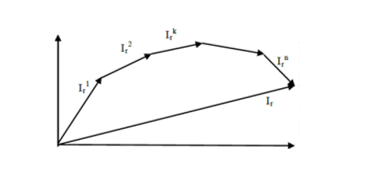
| Total current through any branch due to individual current injection is demonstrated in the following fig.1 |
| In fig. 1 it shows the net current through any branch (say for rth branch Ir) by vectorial addition of the branch currents due to injections at different buses. This is obtained using superposition theorem. |
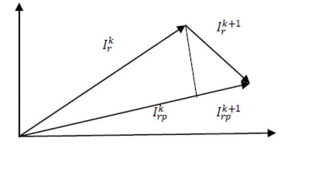
| Orthogonal Current projection component[16] is the key technique in our paper.Net current through any branch due to all all current injections at different buses are supposed to be Ir . Let current contribution to the branch r due to current injection at the kth and (k+1 )th bus is ikr and ik+1r respectively shown in fig.2 |
 |
 |
PROPOSED METHOD
|
| Proposed method will give an idea for reactive power loss allocation in a simple and efficient way. For sake of simplicity we have divided this method into following section viz…. |
| A. POWER EQUIVALENCE AND CIRCUIT THEORY |
 |
 |
| B. REACTIVE POWER LOSS ALLOCATION |
 |
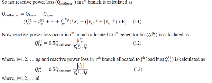
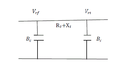
| Where Vrf and Vrt is the from bus and to bus voltage of rth branch having line reactance Xr ,and line charging succeptance Bc |
| In fig.3 it shows the equivalent Π model of a transmission line having line resistance Rr and line reactance Xr .Here it also shows that the from bus voltage and to bus voltage of rth branch is Vrf and Vrt respectively.Here Bc indicates line charging succeptance . |
| So net reactive power loss (Qnetlossr ) in rth branch is calculated as |
 |
NUMERICAL PROBLEMS AND RESULTS ANALYSYS
|
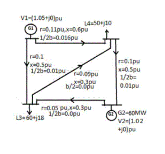
| In fig.4 it shows the sample four bus ring main system to test the validity of the proposed method. Here it also shows the line data and bus data for each of the lines and buses. Here line charging succeptance (b/2) and base MVA is assumed zero and 100 respectively |
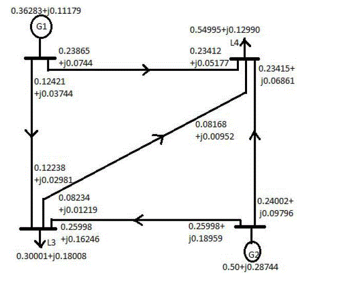
| In fig.5 it shows the power flow diagram of four bus ring main system. Here power flow (flow in and flow out) through each lines obtained from load flow study are shown. Here it also shows the power injections (at generator bus 1 and 2) and power drawn (load bus 3 and 4). |
| For illustration purpose here we have considered sample four bus rig main system whose line data and bus data are given in fig. 4.We have considered convergence tolerance of 0.001 pu and base MVA 100 for load flow study. Power flow through lines and generator (load) bus power injection(drawn) obtained from MATLAB simulation are given in fig. 5. |
| A.BASECASE: Reactive loss allocation to each participants (generators or loads) for each transmission lines are given in table 1. As in table 1 reactive loss allocation of L3 and G2 is higher than of L4 and G1due to the higher power demand or generation. Reactive losses in branch 1-3and 2-3 are MVAR and MVAR respectively ,which is more comparative to other branches due to higher demand and directly fed from G1 and G2. Reactive power loss in line 3-4 is minimum (0.031 MVAR) as power flow is minimum through this line, conforms to the practical situation as both the buses 3 and 4 are load bus. High line charging succeptance in any line(line1-4) comparative to other also reduce reactive power loss by injecting VAR to the same line. |
| B.CASE-1: (L4 is increased by 10 MW):When demand of L4 is increased by 10 MW, from simulation result it is seen that total MVAR loss is increased from 7.923 to 11.505. Increased demand of L4 is met by increased generation of G1 from 52.89MW to 63.58MW.As a result reactive loss allocation of is increased by 1.25 MVAR which is significant than 0.541 MVAR increase in loss allocation of L3(Table2) .As G1 mainly supply the increased demand , so reactive loss allocation of G1 is increased (1.636)by more amount than MVAR of G2(0.151).Power flow through line 1-4 is increased and as a result reactive loss allocation of is increased by 1.9 MVAR, whereas increase in reactive power loss in other lines are not so much prominent as in case of line1-4. |
| C.CASE-2: ( 10 MVAR injected at bus 4):Now at bus 4,10 MVAR is injected keeping other parameter fixed as in case-1.As reactive power is injected locally, L4 meets the reactive power demand mainly from bus 4.There is no need to increase of reactive power generation by more amount at generator bus1and2 as in case-1.As a result reactive loss allocation of G1 and G2 is decreased by 0.2752MVAR and 0.1874MVAR(table:2&3) respectively which reflect that shared of reactive loss of G1 is decreased significantly. Decrease of loss allocations(MVAR) in case-2 with respect to case -1 are 0.306,0.16,0.2752,0.1874 for L4,L3,G1 and G2 respectively. Due to local MVAR generation at bus -4, reactive power flow through line 1-4 is decreased and as a result reactive loss in line 1-4 is decreased by 0.349 MVAR which is more prominent than other lines . Moreover ,power factor(pf) of L4 is improved due to VAR injection and this fact is reflected in the result of less loss allocation of L4,although L3,G1and G2 also get benefit from this VAR injection. |
| It is worth noting that the proposed method can yield negative loss allocation (line1-3 for G2,line3-4 for L3) and consider counter flow which reduces the flow through some branches. In the proposed method remotely located participants are allocated more losses which confirms that this method considers the relative positions of the participants within network. Moreover the proposed method takes into consideration the nature of the loads also ,as lagging power factor load burdens the system more than unity power factor load. Hence in case -2 , reactive loss allocation of L4 is decreased prominently due to VAR injection at bus-4. |
CONCLUSION
|
| So far there is no such efficient transmission loss allocation method that could fit all market structure in different locations .The ongoing research on transmission pricing indicates the criticality and scarcity of a generalized pricing methodology .In some system reactive power cost is included to active power cost and in some other systems power factor is regarded during reactive power cost calculation. But in our proposed method reactive power loss in each branch is allocated to generators or loads proportion to their current projection component and it can be used in pricing market. This paper presents a new transmission loss allocation method applying orthogonal projection concept and having following characteristics |
| 1) Here generators (loads) are converted into current injection when loads (generators) are converted into equivalent admittance conforms to the practical fact and thus it should be adopted. |
| 2) This paper propose loss allocation among participants (generators or loads) proportion to their current projection component ,leading fair way of loss allocation. |
| 3) Likewise incremental loss allocation method and Z bus loss allocation method, this method can yield negative loss allocation to indicate reward to the participants. |
| 4)It is easy to understand and implement numerically. |
| 5)Proposed method allocate losses to participants depending on their utilization of network and is independent of voltage reference bus. |
| 6)It creates incentives or disincentives to participants with respect to their relative location and magnitude. |
Tables at a glance
|
|
|
Figures at a glance
|
 |
 |
 |
 |
 |
| Figure 1 |
Figure 2 |
Figure 3 |
Figure 4 |
Figure 5 |
|
References
|
- D. Kirschen and G. Strbac, “Tracing active and reactive power between generators and loads using real and imaginary currents,” IEEE Trans.On Power Systems, vol. 14, no. 4, pp. 1312–1319, November ,1999.
- A.J.Conejo,J.M.Arroyo,N.Alguacil,andA.L.Guijarro,” Transmission Loss Allocation:A comparison of different practical algorithm, ” IEEETrans. Power Syst,vol. 17, no. 4,pp 571-576,Nov., 2002.
- Niknam T, Arabian H, Mirjafari M (2004) ,” Reactive power pricing in deregulated environments using novel search methods”. IEEEproceeding of third international conference on machine learning and Cybemetics, Shanghai 26–29, pp 4234 4240
- Zhao Y, Irving MR, Song Y “A cost allocation and pricing method for reactive power services in the new deregulated electricity marketenvironment”. IEEE transmission and distribution conference, Asia and Pacific, Dalian, China,pp 1–6,(2005)
- Lin XJ, Yu CW, Chung CY “Pricing of reactive support ancillary services”. IEE Proc Generator Trans Distrib 152:616–622,(2005)
- Muchayim“ A summary of algorithm in reactive power pricing”. Electr Power Energy Syst 21:119–125,(1999)
- Dona VM, Paredes N, “ Reactive power pricing in competitive electric markets using the transmission losses function”. Power Techconference, 10–13 September, Poroto, Portugal, pp 1–6,(2001)
- ChuW, Chen B, “Allocating the costs of reactive power purchased in an ancillary services market by modified Y-bus matrix method”. IEEETrans Power Syst 9:174–180,(2004).
- Ro K , “Calculation of reactive power charges under competition of electric power industries”. ElectrEng 85:169–175, (2003)
- KotsanS , “Efficient pricing of a bundled product of both real and reactive power”. IEEE power system conference and exposition 10–13, pp108–123, (2004)
- Rider MJ, Paucar VL “Application of a nonlinear reactive power pricing model for competitive electric markets”. IEE ProcGeneratTransmDistrib 151:407–415, (2004)
- XieK , “Calculation and decomposition of spot price using interior point nonlinear optimization methods”. Electr Power Energy Syst26:379–388, (2004)
- Chung CY, Chung TS, Yu CW, Lin XJ , “Cost-based reactive power pricing with voltage security consideration in restructured powersystems”. Electr Power Syst Res 70:85–92, (2004)
- Deksnys R, StaniulisR , “Pricing of reactive power services”. Oil Shale Estonian Acad. Publ. 24:363–376, (2007)
- Bialak JW, Kattuman PA, “Proportional sharing assumption in tracing methodology”. IEE ProcGeneratTransmDistrib 151:526–532, (2004)
- Hai-Xia Wang, Rao Liu, and Wei-Dong Li, “Transmission Loss Allocation Based On Circuit Theories and Orthogonal Projection,” IEEETransactions on Power Systems, vol. 24, no. 2,MAY 2009.
|