Keywords
|
| Mobile robot, Elderly people, Surveillance, Remote control. |
INTRODUCTION
|
| Recently the aging society of Japan is a very serious problem. The Cabinet Office, Government of Japan warns that the elderly population will reach at 26.8% of the total population by 2015 [1]. As a matter of fact, the current demand for nursing and care facilities is very high. Therefore, the nursing workload increases which effects the quality for care service. |
| Considering these circumstances, the roboticists are focus on developing robots that can assist nurses during their job or even to substitute them. While robots for drug delivery and waste transportation are deployed in hospitals [2,3,4], only several robots have been developed for surveillance and vital condition checking tasks. Matsui et al. developed a non-contact vital data monitoring system using microwaves for bedridden men [5]. Oda et al. developed a room watching system for the elderly using image processing and sensors embedded in the bed [6]. However, these systems can be utilized only in a single room. If such systems will be installed in each room of the hospital or the care facility it will be very expensive. Therefore, mobile surveillance robots would be a good solution for this problem. A surveillance mobile robot system was developed by Sawashima et al. [7]. The robot system can survey whether or not the elderly is lying down on the floor and move from room to room autonomously. However in case of an emergency, the robot can’t do anything except informing the operator because it has no ability to check a lying elderly’s consciousness and vital conditions. |
| In this work, we present a tele-operated mobile robot system for surveillance of elderly people. In addition to the autonomous navigation the robot is equipped with sensors to check the vital conditions of the elderly person. In addition, the robot sends the sensors data and receives high level commands to and from the operator. Due to the tele-operation, the robot can be also fully controlled by the operator in a long distance. |
OVERVIEW OF DEVELOPED SYSTEM
|
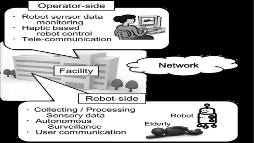
| The main goal of the developed system is to implement it in large hospitals or nursing and care houses. In these facilities, the mobile robot navigates along the corridor and room-to-room autonomously by collecting and processing the environment information. The robot camera image and sensors data are transmitted to the operator PC. In addition, voice communication between the patient and operator is possible. Therefore, the operator can monitor the remote environment and communicate with a patient or elderly in real time. As needed, the operator can check their consciousness and/or simple vital conditions by remote control. Figure1 shows a schematic diagram of our developed system. |
Surveillance Robot
|
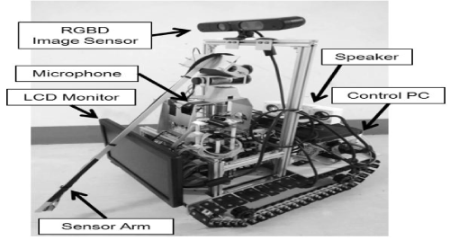
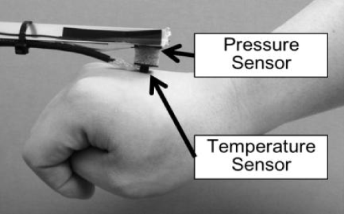
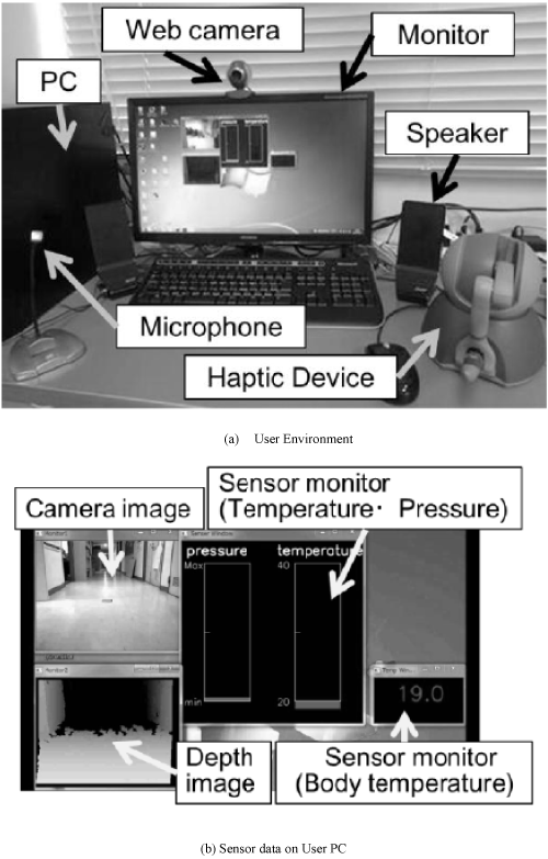
| The developed surveillance robot is shown in Figure 2. The robot has a RGBD image sensor (Xtion Pro LIVE, ASUS) and an arm equipped a temperature sensor and a pressure sensor (Figure 3). The robot also has a microphone, speaker and a small LCD monitor which is used for operator and patient/ elderly communication. The robot length, height, width are 600 mm, 560 mm, 320 mm, respectively. Its weight is 12 kg (including motor and PC batteries). It has 4 degree of freedom (2 crawler, Pitch and Yaw axis sensor arm). The control PC has 1 GB memory and Intel Core i3 CPU. The Ubuntu 12.04LTS OS installed in a SSD. For the user-robot communication and control in a remote distance, we developed a user interface system as shown in Figure 4. The PHANToM Omni haptic device of SensAble Technologies Inc. is used to control the robot manually. In addition, there is a web camera on the users monitor, a microphone and a speaker for interactive communication. The user's PC has an 8GB RAM and an Intel Core i5 CPU, and its OS is Windows 7. On the user's PC monitor, the robot camera image and a depth image are shown. The depth image is utilized by the user during manual control of the robot. In addition, the temperature and pressure sensors data are shown in the operator's monitor. |
SURVEILLANCE NAVIGATION
|
| Developed system has autonomous and manually control mode. And these two modes can be changed at any time, as needed. In the autonomous navigation mode, the robot moves along the regular route by searching the distributed landmarks in the environment at the important points, for example the entrance of the room and passing point in the corridor/room, etc. |
| Autonomous Navigation Mode |
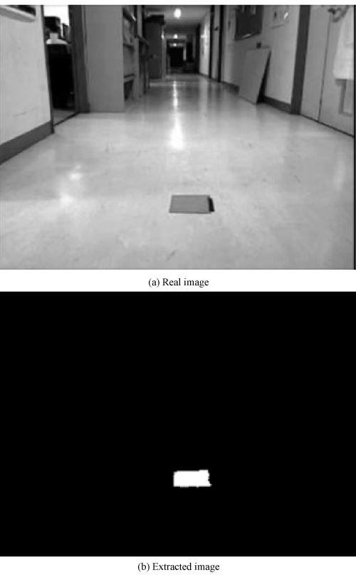
| In this mode, the robot navigates through the corridor. If any landmark becomes visible, the robot moves toward the landmark at regular speed. The landmark is a red color 150x150 mm square. The landmark's center of blob is extracted by RGB image processing (Figure 5 a and b). The reference clawer speed ratio is calculated based on the horizontal offset between the center of image and the blob position, as follows: |
 |
| where, vR and vL are the right/left side crawler reference speed, K1 and K2 are constant values corresponding to the straight and the rotary component, gx is a horizontal coordinate of extracted the center of blob and the WIDTH is the width size of RGB image. |
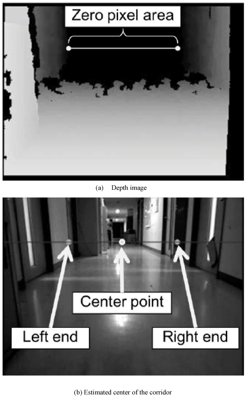
| First, the robot navigates through the center of the corridor using the Depth image. The center of corridor is calculated by using the Depth Image. The upper part in the center of the image is out of measuring range of the Depth sensor (more than 3 m) and the pixels brightness of that part is zero. The right and left walls are recognized by searching non-zero pixels located on the same horizontal line (Figure 6 a). Position of the middle point (Figure 6b) is utilized for correcting the moving direction according to Equation (1) and (2). The landmarks are placed at the entrance of the door. When the landmark becomes visible, the robot reaches the landmark. The robot enters into the room searching for patients through an action order which is defined in advance. |
| The emergency situation is identified by checking the centers of blob between colors of the elderly's clothe and skin (Figure 7b and c). If the distance between blob centers is less than 40 pixels (Figure 7a), the situation is classified as emergency. Therefore, the robot informs the operator, who switch from autonomous navigation mode to the manually control mode. In the manual mode, the user controls the robot motion using the haptic device. In our method, we suppose that all the elderly wear the same color clothe (blue color). |
Manually Control Mode
|
| Manually control mode is utilized during the emergency situations. When the elderly is lying down on the floor, the operator has to check his/her consciousness and vital condition. |
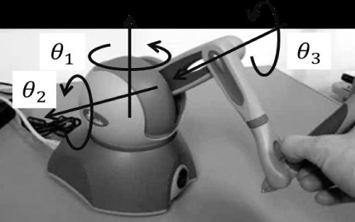
| In this mode, the operator controls the robot motion such as moving speed and direction. In addition, the arm where sensors are mounted is also controlled using the haptic device (Figure 8). In addition to the temperature sensor, the pressure sensor data in are shown in the user's monitor to have a safe operation of the robot. The pressure sensors data show the contact condition between the robot arm and the lying elderly. |
| The reference right and left crawler speed are calculated based on the θ1 and θ3 as follows: |
 |
 |
| where K3 and K4 are constant positive values determined by experiments. θ1max and θ3max are the maximum joint angles, θ1 is ratio of rotation, and θ3 is the ratio of forward/backward crawler speed. The arm motion reference angles θYaw and θPitch are given as follows: |
 |
| where K5 and K6 are also constant positive values determined by experiments |
EXPERIMENTS
|
Experimental Environment
|
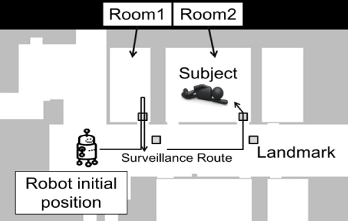
| Figure 9 shows the experimental environment. The robot starts moving along the corridor, enters in room 1 and room 2. In room 1 there is no emergency situation. In room 2, there is a pseudo lying elderly with a blue clothe. Because there is an emergency situation, the user controls robot motion to reach the lying person. As the user does not receive any response when he tries to communicate, the user control the arm motion to check the body temperature using the sensors mounted in the arm. |
Results
|
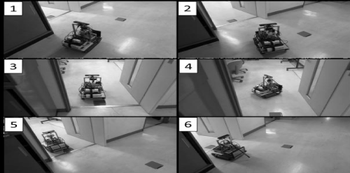
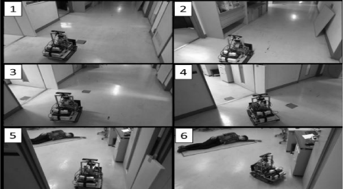
| Figure10 and Figure11 show a video capture of the robot motion during the autonomous navigation. The reference moving speed was set at about 100 [mm/s] in the autonomous navigation mode. |
| Figure 10 shows that the robot navigates safely in the corridor, entering room 1 when the landmark becomes visible. In room 2, the robot was able to find the lying elderly using the RGB image (Figure 11). Than after the user is informed, the user switches to the manual mode. |
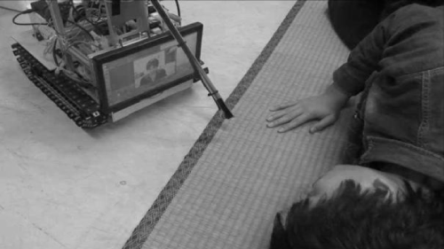
| In the manually control mode, the system was able to check the lying person loss of consciousness because there was no response during real time communication (Figure 12). |
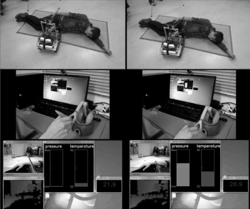
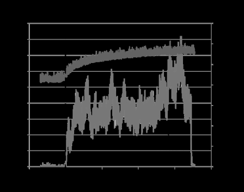
| Next, the sensor arm control performance is evaluated by measuring the body temperature (Figures 13 and 14). By using the haptic device the operator can control the arm safely. Figure 14 shows the graph of the pressure and temperature data. The pressure data prevents an excess of the contact pressure between the temperature sensor and the elderly body. However, the temperature sensor data need some delay time. Because the sensor touches the skin surface, the measured temperature is not exactly the body temperature. |
| The experimental results show that there are often communication delays between the robot and the operator. These delays are due to the robot motion and the deterioration of operability. In addition, these delays may lead to critical incidents. In order to eliminate these negative effects, we suppress the robot motion if a communication delay occurs. |
CONCLUSION
|
| In this paper, we described a tele-operated mobile robot system for the elderly surveillance. The robot operates in the autonomous mode and manual mode. In the autonomous mode the robot navigated in the environment autonomously utilizing the distributed landmarks. On the manually control mode, the operator controlled easily the robot and the robot arm. In addition, the robot utilized the emergency notification function to inform the operator about unusual situations such as an elderly people lying down on the floor. The user utilized graphical and interactive user interfaces and the haptic device during the emergency situations. During the manual control mode the system has useful for the manually control of robot motion. The developed system was evaluated experimentally showing a good performance. |
Figures at a glance
|
 |
 |
 |
 |
 |
| Figure 1 |
Figure 2 |
Figure 3 |
Figure 4 |
Figure 5 |
|
 |
 |
 |
 |
 |
| Figure 6 |
Figure 7 |
Figure 8 |
Figure 9 |
Figure 10 |
|
 |
 |
 |
 |
| Figure 11 |
Figure 12 |
Figure 13 |
Figure 14 |
|
References
|
- Annual Report on the Aging Society: 2014 (Summary), Cabinet Office, Government of Japan.
- Evans JM, HelpMate: an autonomous mobile robot courier for hospitals. Conference proceedings of Intelligent Robots and Systems ’94. ’Advanced Robotic Systems and the Real World’, IROS, vol. 3, pp. 1695 – 1700, 1994.
- M.Takahashi, T.Suzuki, H.Shitamoto, T.Moriguchi, K.Yoshida, “Developing a mobile robot for transport applications in the hospital domain,” Robotics and Autonomous Systems, Vol. 58, pp. 889-899, 2010.
- [4] F. Carreira et al. “i-Merc: A Mobile Robot to Deliver Meals inside Health Services” in Proceedings of the 2006 IEEE International Conference on Cibernetics & Intelligence Systems & Robotics, Automation & Mechtronics, pp. 1-8, 2006.
- Matsui T, Yoshida Y, Kagawa M, Kubota M, Kurita A,“Development of a practicable non-contact bedside autonomic activation monitoring system using microwave radars and its clinical ap4plication in elderly people”, J ClinMonitComput, vol. 27, no. 3, pp. 351-6, 2013.
- Oda A, Fujiwara Y, “Watching System for Care Facilities of The Elderly”, Journal of the Robotics Society of Japan, Vol.28, No.9, pp.1075-1076, 2010.
- Sawashima H, Yano Y, “Development of Elderly people Monitoring System in Care House”, The Resaerch Report, Nara Prefecture Institute of Industrial Development, No.39, pp.6-10, 2013.
|


