Keywords
|
| CUK Converter; SEPIC Converter; hybrid system; renewable energy. |
INTRODUCTION
|
| With increasing concern of global warming and the depletion of fossil fuel reserves, many are looking at sustainable energy solutions to preserve the earth for the future generations. Other than hydro power, wind and photovoltaic energy holds the most potential to meet our energy demands. Alone, wind energy is capable of supplying large amounts of power but its presence is highly unpredictable as it can be here one moment and gone in another. Similarly, solar energy is present throughout the day but the solar irradiation levels vary due to sun intensity and unpredictable shadows cast by clouds, birds, trees, etc. The common inherent drawback of wind and photovoltaic systems are their intermittent natures that make them unreliable. However, by combining these two intermittent sources and by incorporating the system’s power transfer efficiency and reliability can be improved significantly. |
| Virtually all regions of the world have renewable resources of one type or another. By this point of view studies on renewable energies focuses more and more attention. Solar energy and wind energy are the two renewable energy sources most common in use. Wind Energy has become the least expensive renewable energy technology in existence and has peaked the interest of scientists and educators over the world. Photovoltaic cells convert the energy from sunlight into DC electricity. PVs offer added advantages over other renewable energy sources in that they give off no noise and require practically no maintenance. Hybridizing solar and wind power sources provide a realistic form of power generation. Many studies have been carried out on the use of renewable energy sources for power generation and many papers were presented earlier. The wind and solar energy systems are highly unreliable due to their unpredictable nature. In a PV panel was incorporated with a diesel electric power system to analyze the reduction in the fuel consumed. It was seen that the incorporation of an additional renewable source can further reduce the fuel consumption. When a source is unavailable or insufficient in meeting the load demands, the other energy source can compensate for the difference. Several hybrid wind/PV power systems with Maximum Power Point Tracking (MPPT) control have been proposed earlier. They used a separate DC/DC buck and buck- boost converter connected in fusion in the rectifier stage to perform the MPPT control for each of the renewable energy power sources. These systems have a problem that, due to the environmental factors influencing the wind turbine generator, high frequency current harmonics are injected into it. Buck and buck-boost converters do not have the capability to eliminate these harmonics. So the system requires passive input filters to remove it, making the system more bulky and expensive. |
SCHEMATIC REPRESENTATION
|
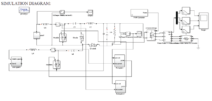
| The Schematic representation is shown in figure which describes the Grid Connected Renewable Energy Using Cuk and Sepic Converter Topology. |
| A.PV ARRAY |
| The PV array is constructed by many series or parallel connected solar cells [8]. Each solar cell is form by a PN junction semiconductor, which can produce currents by the photovoltaic effect. Typical output power characteristics curves for the PV array under different insolation are shown in Fig.2.It can be seen that a maximum power point exists on each power characteristic curve. Therefore, to utilize the maximum output power from the PV array. |
| B.WIND TURBINE |
| Among various types of wind turbines, the permanent- magnet synchronous wind turbine, which has higher reliability and efficiency, is preferred [13]–[16]. |
| The power Pwind of the wind can be derived as |
 (1) (1) |
| where ρ is the air density (kg/m ), A is the area (m ) swep t b y wind blades,Vwind and is the wind speed (m/s). It had been proven that the energy conversion efficiency, Cp, of the wind turbine is a function of the tip speed ratio,λtip , which is defined as |
 (2) (2) |
| where ωr is the rotational speed (rad/sec) of wind turbine blades, is the radius of the area swept by wind turbine blades. A typical curve of the Cp versus λtip is shown in Fig, where the maximum value of Cp is only achieved at a particular tip speed ratio. Since the speed of the wind is not constant, the rotational speed of the wind turbine must be adjustable to ensure a constant tip speed ratio to gain the maximum Cp. The output current change of the wind turbine will cause of the rotational speed as well as λtip to change. Since Cp is a function of λtip , the output power of the wind turbine will change, too. Therefore, by controlling the output current of the wind turbine, the rotational speed of the wind turbine blades can be adjusted to achieve the appropriate tip speed ratio. Eventually, the maximum value of Cp can be obtained and the maximum power can be transferred from the airstream to the wind turbine to produce the maximum electrical power. |
| C.CONVERTER TOPOLOGY |
| 1.CUK converter : |
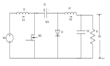
| The Cuk converter is a type of DC-DC converter that has an output voltage magnitude that is either greater than or less than the input voltage magnitude. Cuk converter is actually the cascade combination of a boost and a buck converter. The voltage gain is given by equation |
| Vo= - Vin(D/(1-D)) |
| A non-isolated Cuk converter comprises two inductors, two capacitors, a switch (usually a transistor), and a diode. Its schematic can be seen in fig1. It is an inverting converter, so the output voltage is negative with respect to the input voltage. |
| The capacitor C is used to transfer energy and is connected alternately to the input and to the output of the converter via the commutation of the transistor and the diode . |
| The two inductors L1 and L2 are used to convert respectively the input voltage source (Vi) and the output voltage source (Co) into current sources. Indeed, at a short time scale an inductor can be considered as a current source as it maintains a constant current. This conversion is necessary because if the capacitor were connected directly to the voltage source, the current would be limited only by (parasitic) resistance, resulting in high energy loss. Charging a capacitor with a current source (the inductor) prevents resistive current limiting and its associated energy loss. |
| 2. SEPIC Converter: |
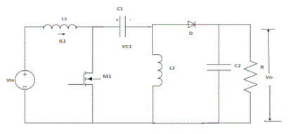
| Single-Ended Primary-Inductor Converter (SEPIC) is a type of DC-DC converter allowing the electrical potential (voltage) at its output to be greater than, less than, or equal to that at its input; the output of the SEPIC is controlled by the duty cycle of the control transistor. |
| A SEPIC is similar to a traditional buckboost converter, but has advantages of having noninverted output (the output has the same voltage polarity as the input), using a series capacitor to couple energy from the input to the output (and thus can respond more gracefully to a short-circuit output), and being capable of true shutdown: when the switch is turned off, its output drops to 0 V, following a fairly hefty transient dump of charge. |
| The schematic diagram for a basic SEPIC is shown in Fig2. As with other switched mode power supplies (specifically DC-to-DC converters), the SEPIC exchanges energy between the capacitors and inductors in order to convert from one voltage to another. The amount of energy exchanged is controlled by switch S1, which is typically a transistor such as a MOSFET; MOSFETs offer much higher input impedance and lower voltage drop than bipolar junction transistors (BJTs), and do not require biasing resistors (as MOSFET switching is controlled by differences in voltage rather than a current, as with BJTs). |
 |
RESULT AND DISCUSSION
|
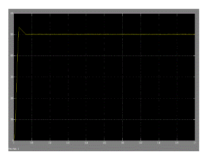
| In this section, simulation results from given to verify that the proposed cuk and SEPIC output stage it can support individual as well as simultaneous operation. Here we get output of integrated wind and PV circuit maximum of 500V DC. |
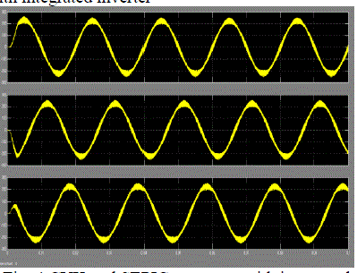
| Here we get output of CUK and SEPIC converter with integrated inverter |
CONCLUSION
|
| In this paper a new multi-input CUK-SEPIC rectifier stage for hybrid wind/solar energy systems has been presented. |
| The features of this circuit are: |
| 1) Additional input filters are not necessary to filter out high frequency harmonics; |
| 2) Both renewable sources can be stepped up/down (supports wide ranges of PV and wind input); |
| 3) MPPT can be realized for each source; |
| 4) Individual and simultaneous operation is supported. |
| In this paper, the operation principle of the proposed inverter has been verified by using been introduced. Simulation results have been presented to verify the features of the proposed topology. |
Figures at a glance
|
 |
 |
 |
 |
| Figure 1 |
Figure 2 |
Figure 3 |
Figure 4 |
|
References
|
- Fused Converter Topology for Wind-solar Hybrid Systems Triptisaha, sushmakakkar and Deependra Kumar School of Electrical, Electronics and Communication Engineering, Galgotias University, U.P., India
- A Hybrid Wind-Solar Energy System: A New Rectifier Stage Topology Joanne Hui*, IEEE Student Member, AlirezaBakhshai, IEEE Senior Member, and Praveen K. Jain, IEEEFellow Department of Electrical and Computer Engineering
- Modeling of hybrid wind and photovoltaic energy system using a new converter topology. Teena Jacob 1and Arun S 2 Department of Electrical and Electronics Engineering, AmalJyothi College of Engineering, Kerala
- Comparison of CUK and SEPIC Converter Applied in Maximum Power Point Tracking for PV System Muhammad SyafeiGozali Department of Electrical Engineering PoliteknikNegeriBatam
- Power Electronic Interface for Grid-Connected PV array using SEPIC Converter and Line-Commutated Inverter with MPPT 1Vijaya Prasad Babu Pilli 1 , MeruguBhanu 2(Department ofElectrical and Electronics Engineering, SCET, Narsapur)
- Analyzing the Sepic Converter by Dr. Ray Ridley, Ridley Engineering
- Multi-Input DC/DC Converter Based on the Multi winding Transformer for Renewable Energy applications Yaow Ming Chen, Member, IEEE, Yuan-Chuan Liu, and Feng-Yu Wu
- Multi-Input Inverter for Grid-Connected Hybrid PV/Wind Power System Yaow Ming Chen, Senior Member, IEEE, Yuan-Chuan Liu, Shih-Chieh Hung, and Chung-Sheng Cheng
- T.-F. Wu, C.H. Chang, Z.-R. Liu, and T.-H. Yu,âÃâ¬Ãâ¢Single-Stage converters for photovoltaic powered lighting systems with MPPT and charging features,âÃâ¬Ãâ in Proc. IEEE APEC, 1998, pp. 1149–1155.
- M. Kolhe, J. C. Joshi, and D. P. Kothari, âÃâ¬Ãâ¢Performance analysis of a directly coupled photovoltaic water-pumping system,âÃâ¬Ãâ IEEETrans. Energy Conv., vol. 19, no. 3, pp. 613–618, Sep. 2004.
|