Keywords
|
| Doubly fed Induction Generator,Grid connected wind farm, GeneticAlgorithm, Asynchronous Generator |
INTRODUCTION
|
| Currently, there is an increasing concern over the environmental impact and sustainability of traditionalfossilfuelled power plants. Because wind energy is one of themost important and promising renewable energy resources in the world, leading to a growing penetration of the windenergy in electrical system, in [1]proposed a wind farm made up with DFIG as a continuous reactive power source to support system voltage control due to the reactive power control capability of DFIG. The particle swarm optimization algorithm (PSO) is utilized to find the optimal reactive power output of wind farm. The main objective of the optimization is to minimize the real power losses of the system and the deviation of the bus voltage in the proposed optimization algorithm, reactive power output of wind farm is utilized as the control variable for loss minimization and voltage profile improvement, in [2] studies the reactive power output optimization of wind farm, and the variability and intermittency of wind speed is considered. The multi-objective reactive power optimization model including network loss, average deviation of voltage system, is popular and widely used for wind power generation due to its several advantages. |
| The effectiveness of the proposed method is demonstrated on IEEE-57 bus system with wind, in [3] the use of genetic algorithms for the resolution of the optimization. problem of the voltages fall and the active losses in a power system including a wind power station by acting on the reactive productions of inductances and capacitors branches connected to the consuming nodesin [4] an improved Genetic algorithm (GA) for reactive power optimization in wind farm. Traditional GA has some drawbacks, such as slow convergence. The coding method, genetic operators, crossover and mutation probability, stopping criterion in iteration has been improved. The reactive power optimization method with improved GA is tested in a MATLAB based simulation model, in [5] developed a wind farm model and concluded that wind farms made up of double fed induction generators constitute an important tool from the voltage regulation point of view. Furthermore, the designed proportional distribution algorithm makes all the generators work under similar conditions and quite far from saturation, which means far from the reactive power generation limits in [6] the power capability limits of doubly fed asynchronous generators. These limits have been obtained by taking into account the maximum stator and rotor currents and the steady state stability limit of the generator, in [7] describe the development of a new algorithm for the solution of a multiobjective problem in power systems with wind farm using Particle Swarm Optimization. Basically, the purpose is to search an optimal operation point of system which allows simultaneous power factor remote control and loss minimization. In [8] described the reactive power capabilities of wind power generator and then discuss reactive power ancillary services issues related to the wind farms in the electricity market. Presently, the doubly fed induction generator(DFIG) systemis popular and widely used for wind power generation due to its several advantages [9]. |
| A detailed view of wind turbine power, energy and torque is given. Different types of generators used in wind farm are also discussed. In the end, an overview of wind power plants is also provided. |
| In present work, a test system is taken and a Wind farm with doubly fed induction generator is connected to one of its nodes. The active power output of the wind farm is used to find the maximum of reactive power capability limits. Then using Reactive power as a control variable, the optimum value of reactive power, for which the losses and voltage deviation are minimized, is determined by Genetic algorithm. |
SYSTEM MODEL AND CONTROL
|
| The model of DFIG consisting of a pitch controlled wind turbine and an induction generator [1]. The stator of the DFIG is directly connected to the grid, while the rotor is connected to a converter consisting of two back-toback PWM inverters, which allows direct control of the rotor currents. Direct control of the rotor currents allows for variable speed operation and reactive power control thus DFIG can operate at a higher efficiency over a wide range of wind speeds and help provide voltage support for the grid.These characteristics make the DFIG ideal for use as a windgenerator. |
| A. DFIG Capability Limits Curve |
| The stator active and reactive power can be expressed as a function of stator current and rotor current [1] |
 |
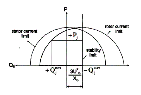
| In the PQ plane, (1) represents a circumference centred at the origin with radius equal to the stator rated apparent power. Equation (2) represents a circumference centred at [−3U2s/Xs, 0] and radius equal to 3XMUS IR / X S.Therefore, given the stator and rotor maximum allowablecurrentsISmax and IRmax, the DFIG capability limits are obtained. |
| Fig.1 shows the composed curve for the DFIG capability limits. Additionally, the steady state stability limit of theDFIG is taken into account, which represented as vertical lineat the [−3U2s/Xs, 0] coordinate. It’s obvious that the DFIGreactive power capability mainly depend on the rotormaximum allowable current IR max. In Fig.1, The DFIG can be able to operate at any point in the intersecting area within the given limits. From this figure, one can observe that when the available active power is farfrom its maximum, the amount of available reactive power is high. |
| The large reactive power control capability of the DFIG making it possible to use DFIG as the continuous reactive power source to support system voltage control. |
| B. Wind Farm Model |
| In this paper, a wind farm model is developed with a DFIG wind turbines connected in parallel. As a result, the total active and reactive power output of the wind farm equal to the sum of the active and reactive power generated by each of the DFIG wind turbine in the wind farm: |
 |
| Where PWF represents the active power output of the windfarm, QWF represents the reactive power output of the windfarm, Pgirepresents the generated active power of each DFIG and Qgi represents the generated or absorbed reactive power of each DFIG. |
| In this paper, it’s assumed that the wind speed at eachDFIG is the same and all of the available active power inwind farm is fed into the distribution network. |
PROBLEM FORMULATION
|
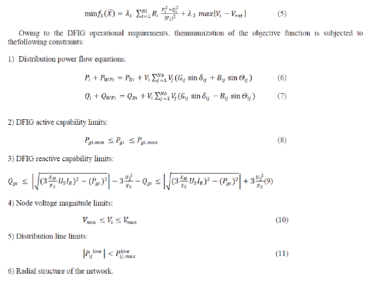
| In this section, wind farm reactive power output optimization has been modelled as a multi objective, nondifferentiable optimization problem. In the proposed optimization algorithm, the objective function consists of two terms: 1) the real power losses of the system, 2) the deviation of the bus voltage. |
 |
GA BASED REACTIVE POWER OUTPUT OPTIMISATION
|
| The beginnings of genetic algorithms can be traced back to the early 1950s when several biologists used computers for simulations of biological systems. However, the work done in late 1960s and early 1970s at the University of Michigan under the guidance of John Holland led to genetic algorithms as they are known today. GA vocabulary is being borrowed from natural genetics. The idea behind genetic algorithms is to do what nature does. Genetic algorithms (GAs) are stochastic algorithms whose search methods inspired from phenomena found in living nature. The phenomena incorporated so far in GA models include phenomena of natural selection as there are selection and the production of variation by means of recombination and mutation, and rarely inversion, diploid and others. Most Genetic algorithms work with one large pneumatic population, i.e. in the recombination step each individual may potentially choose any other individual from the population as a mate. Then GA operators are performed to obtain the new child offspring; the operators are: |
| 1)Selection |
| 2) Crossover |
| 3) Mutation |
| An algorithm is developed to find the optimum value of reactive power output of wind farm and objective function. First the model of the test system is developed in MATLAB/ SIMULINK. Then the simulation results of the test system are used to find the objective function and optimum reactive power. The reactive power output of the wind farm is used as a control variable in Genetic algorithm and an initial population is generated randomly within control variable bounds. Then objective function for each individual is calculated using the result of load flow analysis. The results are then stored after meeting the termination criteria. The algorithm is amalgamation of Genetic algorithm. In Genetic algorithm population is initialized and when it satisfied the constraints by means of mutation and crossover, it assign a new generation which set the value for Reactive power for the given iteration and load flow is run by means of selection. By following this process of crossover, mutation and generation several times the objective function will reach at its minimum value. The Algorithm is explained in steps as: |
| Step1. Initialize the system Data and GA control parameters |
| Step2. Input wind speed and calculate reactive power limit by active power output. |
| Step3.Calculate initial power flow, generate initial population. |
| Step4. Initial population distributes uniformly |
| Step5. Selection, crossover, mutation |
| Step6. Calculate fitness function. |
| Step7. Meet the termination criterion. If not, go to step 5otherwise go to step 8. |
| Step8. Record the results. |
SIMULATION RESULTS
|
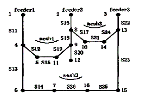
| For modelling of a dynamic system, the system should be fully defined. After building each component, integrate them into a complete model of the system. A three feeder distribution system is used as shown in the Fig. 2 with a base voltage of 0.69 KV. Total system load is 28.7MW and 17.3MVAR. A small wind farm comprising 10 DFIG wind turbines of 900kW, with a power installed of 9MW is connected at node 12 through a rated 23/0.69 kV transformer. |
| The performance parameters of the studied DFIG wind turbine are given in Table 1 |
| The electric parameters of the studied DFIG wind turbine are given in Table 2 |
| A. Available Active and Reactive Power in Wind Farm |
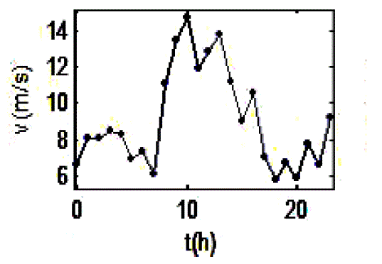
| Fig.3 shows the wind speeds on the wind turbinesconsidered in the simulation. Then the active power output ofDFIG is obtained by means of the power curve. Consideringthe DFIG capability limits curve described in Fig.1, themaximum limits of available reactive power for eachgenerated active power of DFIG wind turbine can becalculated. |
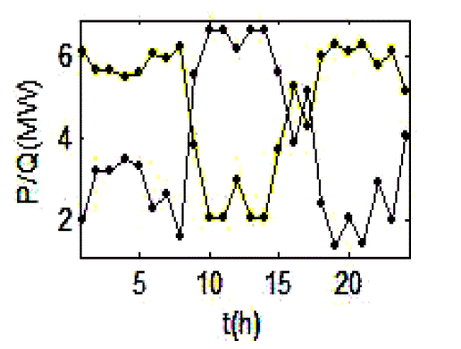
| Fig.4 shows the active and reactive available power in wind farm. From Fig.4, it can be observed that wind farmmade up DFIG wind turbine can generate more reactive power when the available active power decreases. It’s followsthat the wind farm can contribute more significantly to themaintenance of the grid voltage at low speed. |
| B. Results of Optimization |
| The Reactive power output of the DFIG is used as control variable in Genetic algorithm. The objective function which includes minimization of losses and improvement of voltage profile is calculated by means of Genetic algorithm. The Table 3 shows the input values for the optimization toolbox in MATLAB while Table-4 shows the results after optimization through genetic algorithm. Whereas the plot of best fitness, best individual, max constraint and range are drawn by MATLAB Optimization Toolbox. |
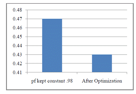
| Comparison between the power losses of the system when the power factor of the wind farm is kept constant at 0.98 and power losses of the system after optimization are shown in Fig.5 |
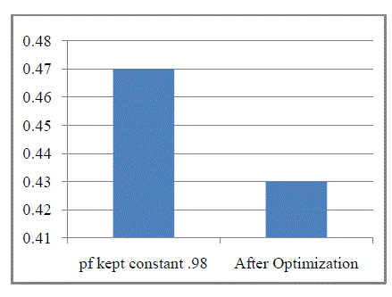
| Comparison between the minimum nodal voltage of the system when the power factor of the wind farm is kept constant at 0.98 and nodal voltage of the system after optimization is shown in Fig. 6. |
CONCLUSIONS
|
| In this paper, a novel approach for reactive power output optimization control of wind farm is proposed. In this new approach, reactive power output of wind farm is utilized as the control variable for losses minimization and voltage profile improvement. The optimal reactive power output of wind farm is efficiently obtained by taken in account DFIG reactive capability limits in the simulations. At last from the results obtained using genetic algorithm, it can be concluded that wind farm can constitute an important continuous reactive power source to support system voltage control. |
ACKNOWLEDGEMENT
|
| The authors would like to thank Prof. (Dr.) P.R. Sharma Chairman and Faculty Members, Department of Electrical Engineering, YMCA University of Science and Technology, Faridabad, for many valuable suggestions. |
Tables at a glance
|
 |
 |
 |
 |
| Table 1 |
Table 2 |
Table 3 |
Table 4 |
|
Figures at a glance
|
 |
 |
 |
| Figure 1 |
Figure 2 |
Figure 3 |
 |
 |
 |
| Figure 4 |
Figure 5 |
Figure 6 |
|
References
|
- Zhao, J.J., Li, Xia., Hao, J.T., Zhang,C.L. and Lu, J.P.,“Wind Farm Reactive Power Output Optimization for Loss Reduction and Voltage Profile Improvements”,IEEE Conference on Power Electronics and Motion Control, pp.1099-1103, 2009
- Wei Xiwen, QiuXiaoyan, XuJian and Li Xingyuan, “Reactive Power Optimization in Smart Grid with Wind Power generator”, IEEE Conference on Power and Energy Engineering, Asia Pacific, pp. 1-4, 2010.
- Krichen,L., Abdallah, H. Hadj, Ouali,A.,“Genetic Algorithms for Optimal Reactive power Compensation of a Power system with wind generators based on Artificial Neural Networks”, Journal of Electrical Systems,Vol.3, pp. 1-12, 2007
- Tao Jin, ZengXiangjun, Zhang Ping and FengKaihui, “Improved Genetic Algorithm Application in Reactive Power Optimization of Wind Farm”, The International conference on Electrical Engineering, pp. 1-4, 2009.
- Tapia, A., Tapia, G.,Ostolaza, J.X., “Reactive power control of wind farms for voltage control applications, Renewable Energy”, Vol.29,No.3, pp.377–392, 2004.
- Martin, D. Santos,Arnaltes,S.,Amenedo,J.L.R.,“Reactive power capability of doubly fed asynchronous generators”, Electric Power Systems Research, Vol.78, No.11, pp.1837–1840, 2008.
- Oliveira, C.B.M., De Medeiros, ManoelFirmino, Jr., De Oliveira, Jose Tavares , “New Method based in Particle Swarm Optimization for Power Factor Remote Control and Loss Minimization in Power Systems with Wind Farms Connected”, IEEE International Conference on Intelligent System Applications to Power Systems, pp.1-6, 2009.
- Singh, Sri Niwas, Ostergaard, Jacob, Singh, Bharat , “Reactive Power Capability of Unified DFIG for Wind Power Generation”, IEEE Power and Energy Society General Meeting, pp. 1-7, 2010.
- Johnson, Gary L. “Wind Energy Systems”, Electronic Edition, 2006.
- Texas Comptroller of Public Accounts, “The Energy Report”, Ch-11, May 2008.
- World Wind Energy Association, “World Wind Energy Report 2009”, March 2010.
- Global Wind Energy Council, Indian Wind Energy Outlook 2009, Sep 2009.
- Tegou, L.I., Polatidis,H.,andHaralambopoulos, D.A., “Distributed Generation with Renewable Energy Systems: The spatial Dimension for an Autonomous Grid”, Conference of the European Regional Science Association, France, pp. 1-20, 2007.
- Civanlar, S., Grainger,J.J.“Distribution Feeder Reconfiguration for Loss Reduction”, IEEE Trans Delivery, Vol.3, No.3, pp.1217-1223,
|