Keywords
|
| Messung PLC, SPM, MIG Welding, Shock Absorber, Mitsubishi HMI. |
INTRODUCTION
|
| Industrial Automation has gained importance owing to the ever-increasing demand for more productivity, better quality standard, better accuracy and optimum utilization of available resources and manpower. In India, Gabriel is the largest manufacturer of Shock Absorbers. In accordance with the huge productivity demands of their Shock Absorbing Units for Hyundai Motors, Gabriel India has planned a Special Purpose Machine (SPM) called “MIG WELDING SPM” in their production unit. The main aspect of the project is to automate the process of MIG Welding which is a crucial step in the production of shock absorbers. |
RELATED WORK
|
| The related approaches include design of automatic Welding machine based on PLC. This method presents an automatic welding machine used for the carbon dioxide gas welding, with the mechanical structure designed, and the working process of the automatic welding machine analyzed. Experimental operation results show that PLC-controlled automatic welding machine can improve welding quality and efficiency, reduce labour intensity and bring huge economic benefits [2]. Other methods include forward and reverse modelling in MIG Welding process using fuzzy logic-based approaches. It is an attempt to carry out the forward and reverse modelling of the MIG welding process using fuzzy logic-based approaches[3]. |
PREVIOUSLY EXISTING METHODS
|
| The Methodology which was used prior to the automated system included Welding which was done by means of hand held Welding guns. This method had less accuracy and precision as compared to the automated system of welding. The process was time consuming and it had demanding man power. Many such factors resulted in less production. Also, the welding process which was implemented had safety issues. The automated method was proposed as a result of the less amount of production as well as the consideration of the safety issues of the workers. The process of MIG welding implemented to weld the knuckle bracket on the circular shaft of the shock absorber is achieved by means of a MessungNexgen 5000 PLC. It has about 1000 inputs and 1000 outputs. The PLC programming is done by means of a ladder diagram. The following Table 1 illustrates the comparison of various key performance parameters between the previously existing system and the currently existing method. |
| (A) Amount of Production: The amount of production in the previously existing method was severely low owing to the handheld welding process. The efficiency of the welding, also, was not up to the mark. The automated control system implements an efficient algorithm for the overall synchronization of the sequence of operations in the SPM. As a result, the amount of production is increased as compared to the previously existing method. |
| (B) Quantity of Manpower: A comparison between the two systems indicates that more number of workers were needed in the previously existing methods. The automated method, however, demands less manpower which ultimately resulting in lower costs for manufacturing. |
| (C) Time Consumed: The previous system implemented a time consuming method for welding, that too with less accuracy and precision. The automated system does not have such constraints owing to the high speed switching operation performed by the PLC. |
| (D) Accuracy: The Accuracy is a vital performance parameter which decides the overall efficiency of the system. The automated system, with the help of perfectly aligned Welding guns, perform welding with the highest precision and accuracy as compared to the previously existing method. |
DESCRIPTION OF SYSTEM AND WORKING
|
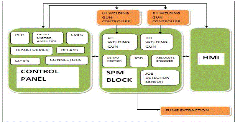
| The Control system consists of 3 main blocks namely the SPM block, the Control Panel block and the HMI. |
| (A) SPM Block: The SPM block is the block in which the job is placed. It consists of a cradle on which the job rests and there are clampers at the end of the job to hold it. The SPM block consists of the servo motor which is used to rotate the job according to the required orientation angle. Also it includes the left and right Welding guns present in the SPM block which play a vital role of performing welding on the job. The absolute encoder present in the block keeps a record of the number of rotations of the shaft. A job detection sensor does the initial job of detecting the job present on the cradle. |
| (A) Control Panel: The Control Panel block includes the various components like PLC, Servo Motor Amplifier, SMPS, Transformer, Relays, and Connectors. The PLC is the heart of the controlling action provided to the system. The PLC being used is Messung Nexgen-5000 PLC. It has about 1k inputs and outputs. The Servo Motor amplifier is used to control the servo motor present in the SPM block. The SMPS is used to provide a 24VDC supply to the PLC. The Transformer is used to power up the different components which require an AC supply. Finally, the relays and connectors serve the function of switching ON/OFF which is essential in the controlling action. |
| (B) HMI: The Human Machine Interface is used to achieve an active communication between the system and the operator. The operator can set the values of various parameters like the rotating angle of the servo motor along with the various modes of rotation. The HMI provides information about various key parameters like the operating temperature, the count of the finished jobs and the mode of operation of the system. The HMI being used is a Mitsubishi GT-1020 HMI. It has a STN monochrome Liquid Crystal Display, a 3.7’’ Diagonal Display along with various colored LED’s for indicating different states of the machine. |
| (C) Fume Extractor: The Fume Extractor evacuates the gas which is been produced during the Welding operation away from the machine. |
| (D) Welding Gun Controllers: The left and the right Welding gun controllers control the respective Welding guns present in the SPM block. It receives the input signals from PLC and instructs the guns accordingly. |
WORKING OF THE SYSTEM
|
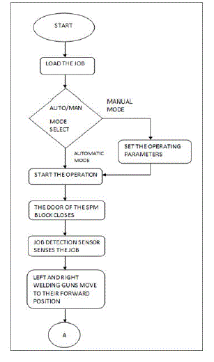
| The flow of working of the system is in the following manner: |
| [1] The System is turned on by the operator. |
| [2] Initially as soon as the machine is started, the door to the SPM block is open. The operator loads the job inside the SPM block. |
| [3] The operator selects the Auto/Manual mode of working of the system with the help of HMI. The manual mode enables the operator to customize the operating parameters of the system in the HMI; the system can be tested for different operating conditions in the manual mode. The Automatic mode starts the operation automatically as soon as it is selected. The door of the SPM block closes as soon as the operator is done with selecting the mode of operation followed by pressing the start button of the machine. |
| [4] The Automatic mode operation includes the following sequence of operation: |
| (A) The job detection sensor senses the job and sends the corresponding output signal to PLC. The PLC reads this input signal and implements it in the ladder diagram, generating a new output signal. |
| (B) PLC sends this output signal to the servo motor and welding gun controllers simultaneously. |
| (C) The welding guns move from their home position to the forward position. Also, at this stage, the absolute encoder is initialized. |
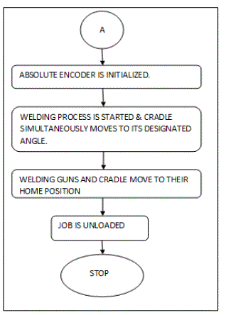
| (D) The Welding gun controller sends the signal to start welding and simultaneously, cradle moves to its designated angle during the Welding process. |
| (E) Absolute encoder measures the angle by which the cradle has been rotated and it informs the PLC regarding the same. |
| (F) The PLC waits for the cradle to rotate to its required angle and it immediately sends a signal to the welding gun controllers to stop the welding process as soon as the cradle achieves its required angle. |
| (G) The Welding guns and the cradle move to their home position. |
| (H) The door to SPM block opens and the job is unloaded by the operator. |
| (I) This is the end of the first cycle, the cycles can be continued if the set of operating parameters required for the next cycle are the same as the previous cycle. |
| The following flowchart illustrates the working explained above: |
HARDWARE IMPLEMENTATION
|
| A. Input Devices – |
| 1) Job Detection Sensor: The Job Detection Sensor is used to check whether the job is loaded on the cradle or not. If the job has been loaded, it informs the PLC regarding the same. |
| 2) Absolute Encoder: The Absolute encoder has the primary function to count the number the rotations of the shaft. For each rotation, it generates some pulses which are used to measure the angle by which the shaft is been rotated. The absolute encoder informs the PLC as soon as the cradle has achieved its designated angle during welding process. |
| B. Output Devices – |
| 1) Servo Motor: The Servo motor performs the primary function of rotating the cradle. It is controlled by the servo motor amplifier which is presented in the control panel. The Servo Motor can be used to rotate the cradle at any desired angle |
| 2) Welding Guns: The right and left hand side welding guns present in the system perform the function of welding theknuckle bracket on the shaft. Both of them are controlled by the Welding gun Controller |
CONCLUSION
|
| In this paper, we presented a novel approach for MIG welding which proves to far better as compared to the previously existing methods. The use of PLC for controlling action of the system effectively results in increased production, less time consumption and better safety for the employees. |
FUTURE SCOPE
|
| The application can be extended by using wireless technologies such as ZIGBEE, GSM, or RFID. This will help the operator in tracking the status of the system even from a different location. |
ACKNOWLEDGMENT
|
| We are grateful to our Internal Project guide, Mrs.SuvarnaK.Gaikwad for her continuous support and motivation regarding the project. We also thank our External project Guide, Mr. Ganesh Toke for helping us solve the technical difficulties which were faced during the entire phase of the project. |
Tables at a glance
|
 |
| Table 1 |
|
Figures at a glance
|
 |
 |
 |
| Figure 1 |
Figure 2 |
Figure 3 |
|
References
|
- Georg Frey and LotharLitz, “Formal Methods in PLC Programming”, IEEE Conference on Systems Man and Cybernetics SMC 2000,pp.1-4,2000.
- Ai-min Li, Chuan-hui Zhang, Hai-lin Li, Zhi-yang Xu, Xiao-hui Chen, Guang-le Qin, Sheng-wei Ye, “Design of Automatic Welding Machine Based on PLC”, Fourth International Conference on Intelligent Computation Technology and Automation 2011, pp 627-630, 2011.
- J.P. Ganjigatti, Dilip Kumar Pratihar, “Forward and reverse modeling in MIG welding process using fuzzy logic-based approaches”, Journal of IIntelligent and Fuzzy Systems, Volume 19, Number2/2008.
- Villafuerte, J., “Advances in robotic welding technology”, Welding J. 84(1) 2005, pp.28-33.
- B. Mulman, T. Devinder, and W. Gi-Nam., “Generation of PLC Ladder Diagram Using Modular Structure”, International Conference on Computational Intelligence for Modelling, Vienna, pp. 1194-1198,Oct 2008.
|