Keywords
|
| Discrete Wavelet Transformation, Xilinx ISE, , System Security. |
INTRODUCTION
|
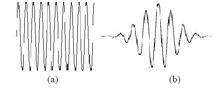
| The fundamental idea behind wavelets is to analyze according to scale. Indeed, some researchers in the wavelet field feel that, by using wavelets, one is adopting a perspective in processing data. Wavelets are functions that satisfy certain mathematical requirements and are used in representing data or other functions. This idea is not new. Approximation using superposition of functions has existed since the early 1800's, when Joseph Fourier discovered that he could superpose sines and cosines to represent other functions. However, in wavelet analysis, the scale that we use to look at data plays a special role. Wavelet algorithms process data at different scales or resolutions. Fourier Transform (FT) with its fast algorithms (FFT) is an important tool for analysis and processing of many natural signals. FT has certain limitations to characterize many natural signals, which are non-stationary (e.g. speech). Though a time varying, overlapping window based FT namely STFT (Short Time FT) is well known for speech processing applications, a timescale based Wavelet Transform is a powerful mathematical tool for non-stationary signals. Wavelet Transform uses a set of damped oscillating functions known as wavelet basis. WT in its continuous (analog) form is represented as CWT. CWT with various deterministic or non-deterministic bases is a more effective representation of signals for analysis as well as characterization. Continuous wavelet transform is powerful in singularity detection. A discrete and fast implementation of CWT (generally with real valued basis) is known as the standard DWT (Discrete Wavelet Transform).With standard DWT, signal has a same data size in transform domain and therefore it is a non-redundant transform. A very important property was Multi-resolution Analysis (MRA) allows DWT to view and process. |
| The wavelet analysis procedure is to adopt a wavelet prototype function, called an analyzing wavelet or mother wavelet. Temporal analysis is performed with a contracted, high-frequency version of the prototype wavelet, while frequency analysis is performed with a dilated, low-frequency version of the same wavelet. Because the original signal or function can be represented in terms of a wavelet expansion (using coefficients in a linear combination of the wavelet functions), data operations can be performed using just the corresponding wavelet coefficients. And if you further choose the best wavelets adapted to your data, or truncate the coefficients below a threshold, your data is sparsely represented. This sparse coding makes wavelets an excellent tool in the field of data compression. Other applied fields that are making use of wavelets include astronomy, acoustics, nuclear engineering, sub-band coding, signal and image processing, neurophysiology, music, magnetic resonance imaging, speech discrimination, optics, fractals, turbulence, earthquake-prediction, radar, human vision, and pure mathematics applications such as solving partial differential equations. |
DESCRIPTION OF THE WAVELET THEORY
|
| A ‘wavelet’ is a small wave which has its energy concentrated in time. It has an oscillating wavelike characteristic but also has the ability to allow simultaneous time and frequency analysis and it is a suitable tool for transient, nonstationary or time-varying phenomena. |
| The wavelet analysis procedure is to adopt a wavelet prototype function, called an ‘analyzing wavelet’ or ‘mother wavelet’. Temporal analysis is performed with a contracted, high frequency version of the prototype wavelet, while frequency analysis is performed with a dilated, low frequency version of the same wavelet. Mathematical formulation of signal expansion using wavelets gives Wavelet Transform (WT) pair, which is analogous to the Fourier Transform (FT) pair. Discrete-time and discrete-parameter version of WT is termed as Discrete Wavelet Transform (DWT). |
| Compactly supported wavelets are functions defined over a finite interval and having an average value of zero. The basic idea of the wavelet transform is to represent any arbitrary function f(x) as a upperposition of a set of such wavelets or basis functions. These basis functions are obtained from a single prototype wavelet called the mother wavelet ψ(x), by dilations or scaling and translations. Wavelet bases are very good at efficiently representing functions that are smooth except for a small set of discontinuities. The Discrete Wavelet Transforms (DWT) have been widely used in many applications like image compression, signal processing, speech compression because of their Multiresolution of signals with localization both in time and frequency. In the past, much architecture have been proposed aimed at providing high – speed 2-D DWT computation with the requirement of utilizing a reasonable amount of hard ware resources. These architectures can be broadly classified into two types named Non Separable 2-D DWT and Separable 2-D DWT . |
Non separable 2-D DWT
|
| In non separable architectures the 2-D transforms are computed directly by using 2-D filters. The two non separable architectures, one using parallel 2-D filters and the other an SIMD 2-D array, both based on a modified RPA. In non separable method internal line buffers are use to store the boundary data among neighbour blocks such as to keep the required external frame memory bandwidth as low as the separable method. However, the external memory access would consume the most power and become very sensitive in the case of system on chip. In addition, the required external memory bandwidth of the non-separable is more than the double of the separable method. The 2-D transforms are computed directly by using 2-D filters. Two non-separable architectures, one using parallel 2-D filters and the other an SIMD 2-D array, both based on a modified RPA. In the former architecture, a high degree of computational parallelism is achieved at the expense of less efficient hardware utilization, whereas the latter architecture requires a reconfigured organization of the array as the processing moves on to higher decomposition levels. A number of parallel FIR filters with a polyphase structure are used to improve the processing speed at the expense of increased hardware. An effort to provide a reduced count of multipliers and to facilitate the processing of the boundary data, have proposed architecture that is a pipeline of one stage of parallel multipliers and two stages of accumulators to perform the accumulation tasks of the filters in each of the two directions. |
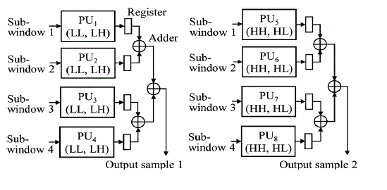
| Fig. 3 gives the block diagram of the pipeline showing all the components required by the three stages. Note that the data flow shown in this figure comprises only the LL-sub band data necessary for the operations of the stages. The HH, HL and LH sub- band data are outputted directly to an external memory. Now, we give details on the structure of the data scanning unit to scan the 2-D data and establish four distinct sub-windows, as well as on the distribution of the filtering operations to the processing units in each stage. |
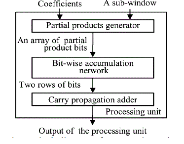
| In order to obtain the output sample corresponding to a given sub-window, the bits of the partial products must be accumulated vertically downward and from right to left by taking the propagation of the carry bits into consideration. The task of this accumulation can be divided into a sequence of layers. The shortest critical data path can be achieved by minimizing the number of layers and the delay of the layers. In each layer, a number of bits consisting of the partial product bits and/or the carry bits from different rows need to be added. This can be done by employing in parallel as many bit-wise adders as needed in each layer. The idea behind using bit-wise adder is to produce to the extent possible the number of output bits from a layer is smaller than the number of input bits to that layer. This can be done by using full adders and specifically designed double adders, in which the full adder consumes 3 bits and produces 2 bits (one sum and one carry bits) whereas the double adder consumes two pairs of bits from neighbouring columns and produces 3 bits (one sum and two carry bits/two sum and one carry bits). The two types of adders have equal delay, and are efficient in generating carry bits and compressing the number of partial products. |
Separable Method
|
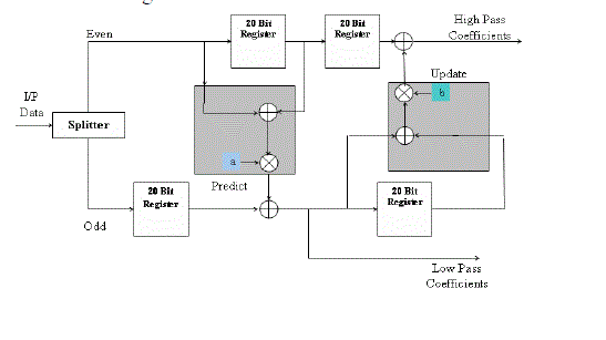
| The separable method is the most straight forward implementation method. In separable method, a 2-D filtering operations, one for processing the data row-wise and the other column-wise. In this method the intermediate coefficients stores in a frame memory first. Then it performs 1-D DWT in other direction with these intermediate coefficients to complete one-level 2-D DWT .Because the size of this frame memory is usually assumed to off chip. However, the separable method performs 1-D DWT in both directions simultaneously. Thus in separable architectures, in which a 1-D filtering structure is used to perform the 2-D DWT, have an additional requirement of transposing the intermediate data between the two 1-D filtering processes. Hence the separable method does not require a frame memory to store the intermediate data. Instead, some internal line buffers are used to store the intermediate data, and the required size is proportional to the image width. A low-storage short-latency separable architecture in which the row wise operations are performed by systolic filters and the column operations by parallel filters. The architecture of2- D DWT is shown in below figure 4. |
| The splitter decomposes the input signal into two sub band signals, even and odd. The even signal represents the high frequency (or coarse) part of input, while the odd signal represents the low frequency (or detail) part of input. As shown in the figure, the output of each register is then delayed by one clock pulse to obtain the delayed signal. By using 1-D DWT architecture the input data divided into even coefficients and odd coefficients. |
PROPOSED PIPELINE ARCHITECTURE
|
| In a pipeline structure for the DWT computation, multiple stages are used to carry out the computations of the various decomposition levels of the transform [4]. The computation corresponding to each decomposition level needs to be mapped to a stage or stages of the pipeline. In order to design a pipeline structure capable of performing a fast computation of the DWT with low expense on hardware resources and low design complexity, an optimal mapping of the overall task of the DWT computation to the various stages of the pipeline needs to be determined. Any distribution of the overall task of the DWT computation to stages must consider the inherent nature of the sequential computations of the decomposition levels that limit the computational parallelism of the pipeline stages, and consequently the latency of the pipeline. Further, in order to minimise the expense on the hardware resources of the pipeline, the number of filter units used by each stage ought to be minimum and proportional to the amount of the task assigned to the stage. |
| A straight forward of mapping of the overall task of the DWT computation to a pipeline is one-level to one-stage mapping, in which the tasks of J decomposition levels are distributed to J stages of the pipeline. However, dividing a stage of the one-level to one stage pipeline into multiple stages would require a division of the task associated with the corresponding decomposition level into sub-tasks, which in turn, would call for a solution of even a more complex problem of synchronization of the sub-tasks associated with divided stages. On the other hand, merging multiple smallsize stages of the pipeline into one stage would not create any additional synchronization problem. As a matter of fact, such a merger could be used to reduce the overall number of filter units of the pipeline. |
| Synchronization of stages-The stages of pipeline need to be synchronized in such a way that each stage starts the operation at an earliest possible time when the required data become available for its operation. Once the operation of a stage is started, it must continue until the task assigned to it is fully completed. |
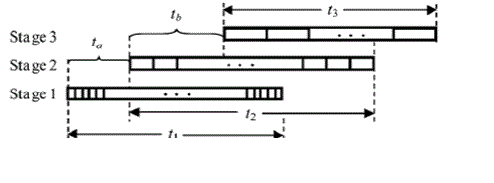
| Consider the timing diagram given in Fig. 3.6 for the operation of the three stages, where t1, t2 and t3 are the times taken individually by stages 1, 2 and 3, respectively, to complete their assigned tasks, and ta and tb are the times elapsed between the starting points of the tasks, by stages 1 and 2, and that stages 2 and 3 respectively. |
| Note that the lengths of the times t1,t2 and t3 to complete the tasks by individual stages are approximately the same, since the ratios of the tasks assigned and the resources made available to the three stages are the same. The average times to compute one output sample by stages 1,2 and 3 are in the ratio 1:4:8. In Fig. 2 the relative widths of the slots in the three stages are shown to reflect this ratio. Our objective is to minimise the total computation time ta+tb+t3 by minimizing t,t and t individually. |
RESULTS
|
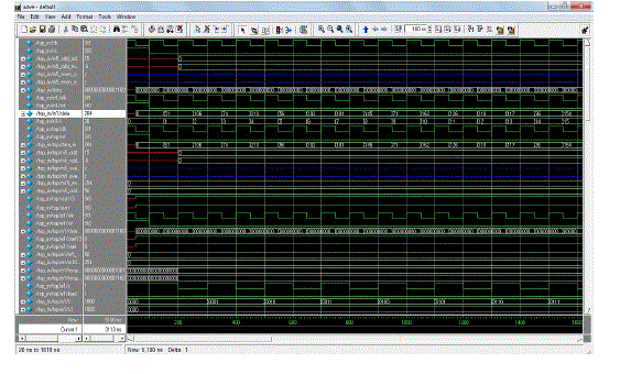
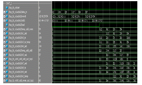
| The results pertaining to the proposed model are mentioned in this chapter. The typical input data is mentioned in the Fig.8design process. |
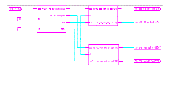
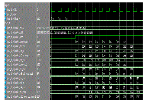
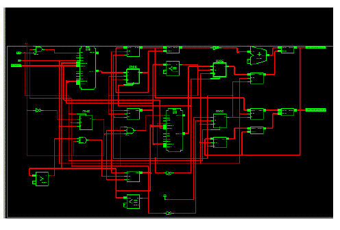
| The simulation results of the DWT-1 and DWT-2 are as shown in the Fig.9 and Fig.10. THe results screen shots reveal the proposed model performance with the input data mentioned in the Fig.8. The RTL schematic layout design are mentioned in Fig.11. |
CONCLUSION
|
| It is concluded that in DWT, the most prominent information in the signal appears in high amplitudes and the less prominent information appears in very low amplitudes. In this paper, presents how signal decomposition is happen through separable DWT architecture. Separable pipeline architecture for fast computation of the 2-D DWT with a less memory and low latency is presented. The low latency and less memory is achieved by proper designing of two 1-D DWT filtering processes and also efficiently transferring the data between the two 1-D DWT architectures. This architecture is simulated, synthesized and implemented by VERILOG language using XILINX ISE Tool. In future it can be applied to frames also. |
Figures at a glance
|
 |
 |
 |
 |
 |
| Figure 1 |
Figure 2 |
Figure 3 |
Figure 4 |
Figure 5 |
 |
 |
 |
 |
 |
| Figure 6 |
Figure 7 |
Figure 8 |
Figure 9 |
Figure 10 |
 |
| Figure 11 |
|
References
|
- Yao TianRen. Modern digital signal processing. Huazhong University of science and technology press.1996.
- He Xiaohai.Image communication. Xidian university press.2005.
- V. N. Kopenkov and V. V. Myasnikov, “Fast Algorithms of a Local Discrete Transform with Haar Basis,” in Proceedings of Scientific andTechnical Concern with International Participation, 2006.
- P. N. Podkur, “On Constructing Some Types of Wavelets with the Scaling Coefficient N” Electronic Scientific J.“Sdelano v Rossii,” 2006,Electronic Scientific J. “Made in Russia,” 2006.
- Castleman, “Digital Image Processing”, Pearson Education India, 2007.
- KianKeeTeoh, Ibrahim H, Bejo S.K, “Investigation on several basic interpolation methods for the use in remote sensing application”, IEEEpaper on Innovative Technologies in Intelligent Systems and Industrial Applications, 2008.
- Lemieux A and Knoll E, “Digital Image Resolution”, IEEE International Proceedings on Communication, 1999.
- Gribbon K.T, Bailey, D.G. “A Real- Time Bilinear Interpolation”, IEEE International Workshop on Electronic Design Test and Applications,2004.
- Gonzalez, Richard E. Woods, “Digital Image Processing”, Second Edition.
- Ralf Steinmetz and KlaraMahrstedt, “Multimedia Computing, Communication and Applications”, 2001.
- Galli A.W, G.T Heydt and P.F Ribeiro, “Exploring the Power of Wavelet Analysis”, IEEE Computer Application in Power, 1996.
|