A long-distance imaging system can be strongly affected by atmospheric turbulence. Here a novel method is suggested for justifying the effects of atmospheric distortion on practical images, especially airborne turbulence which can cruelly corrupt a region of interest (ROI). In order to extract precise details about substance behind the distorted layer, a simple and capable frame selection method is proposed to select informative ROIs only from good worth frames. The ROIs in each frame are then registered to further reduce offsets and distortions. The space-varying alteration problem is solved using region-level fusion based on the double density- tree discrete wavelet transform DD-DWT. Finally, for applying double density dual tree wavelet transform is coming to better results. This is capable of estimating the quality in both full and no reference scenarios. The proposed method is shown appreciably to outperform accessible methods, providing enhanced situational attentiveness in a range of real time surveillance scenarios.
INTRODUCTION |
| Atmospheric turbulence is obviously happening phenomenon that can brutally humiliate the visual quality
of video signals during success. There are many impressive distortions such as fog or haze which cause disparity and
turbulence due to temperature variations or aerosols. Video footage in public areas is affected by such atmospheric
distortions which result in blurring, dithering and warping of image of objects in the scene. In strong turbulence,
blurring effects which are nearby in the video imagery, scintillation producing small-scale intensity fluctuations in the
scene as well as shear effect is observed. Due to shearing effect, different parts of objects are superficial to be moving
in different directions. These effects are mainly found at locations such as hot roads and deserts. This is particularly a
problem close to the earth in hot environments and also in long range surveillance applications where images can be
acquired over distances up to 20 km. It is found difficult to interpret information behind the distorted layer due to
turbulence effects. This leads to faster and greater micro scale changes in the air’s refractive index. In situations when
the ground is hotter than the air above it, the air is heated and forms horizontal layers. Due to this addition in the
temperature, the difference of ground and air is observed, so thickness of layer shrinks and air layer move upwards
leading to change in the air’s refractive index. Hence, there has been significant research activity attempting to
faithfully reconstruct this useful information using various methods. |
PROJECTED MITIGATION SCHEME |
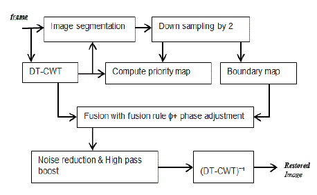
| Here suggested a new synthesis method for sinking the property of atmospheric turbulence as depict . First
before applying synthesis, a subset of selected images or ROIs must be associated. Here a
new design approach is introduced for distorted images. As accidentally distorted images do not provide matching
features, so cannot use conventional methods to find identical features. Instead, applying a morphological image
processing technique, namely erosion, to the ROI (or whole image) based only on the most revealing frames is used. |
| These are preferred using a quality metric based on sharpness, intensity, similarity and ROI size. Then non-rigid image
registration is useful. Hence can employ a region based fusion. |
A. ROI Association |
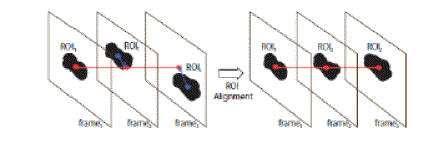
| The ROI (or ROIs) is manually marked in
the first frame. Then the histogram generated from the selected ROI and the surrounding area, is employed to find an
Otsu threshold which is used to convert the image to a binary map. An erosion process is then applied and the areas
connected to the edge of the sub-image are removed. This step is performed iteratively until the area near the ROI is
isolated. The same Otsu threshold with the same number of iterations is employed in other frames. The centre position
of each mask is then computed. If there is more than one isolated area, the area closest in size and location to the ROI
in the first frame is used. Finally, the centre of the mask in each frame is utilized to shift the ROI and align it across the
set of frames (Fig. 1). Note that the frames with incorrectly detected ROIs will be removed in the frame selection
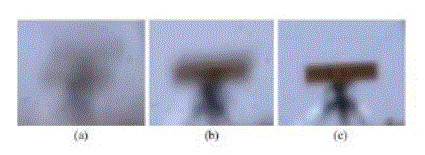
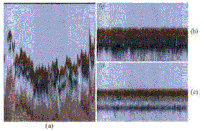
process (Section II-B). These frames are generally significantly different from others. Fig.2 demonstrates the
improvement due to the proposed ROI alignment approach. The left side image represents the average frame of the
whole Number Plate sequence and it reveals high variation due to camera movement which significantly impacts on
image quality more than the turbulence. |
B. Frame Assortment |
| In CLEAR, not all frames in the progression are used to reinstate the image since the low quality frames (e.g. the very
blurred ones) would possibly corrupt the fused result. |
| 1) Sharpness: Gn is an essential image quality factor because it describes about the image clarity, sharpness etc... |
| 2) Intensity Resemblance: Sn is employed to eliminate outliers. This operates under the hypothesis that most frames in
the sequence contain fairly similar areas. Frames with significantly different content to others are likely to be greatly
distorted. |
| 3) Detect ROI Size: An is the total number of pixels controlled in the ROI. |
| C. Image Muster Muster of non-rigid body using the phase shift property of the DT-CWT, as proposed is employed.
This algorithm is based on phase-based multidimensional volume registration,
which is robust to noise and temporal intensity variations. |
| D. Image Synthesis |
| Due to its shift invariance direction selectivity and multiscale properties, the DT-CWT is widely used in image fusion
where useful information from a number of source images are selected and combined into a new image. |
| E. Post Dispensation |
| 1) Disparity Enhancement: In many cases, atmospherically degraded images also suffer from poor contrast due to
severe haze or fog. In such cases, pre or post-processing is needed to improve image quality. Numerous techniques
have been proposed for haze reduction using single images . Hence can employ a simple and fast method using contrast
limited adaptive histogram equalization (CLAHE) . |
| 2) Other Probable Enhancements: Generally the embedded constraint Ag in this approach produces sharp results;
however, in cases which are out-of-focus or which lack a “lucky region”, post-processing may be required to further
sharpen the images. A number of sharpen methods exist. |
PROPOSED METHOD |
| Double Density Wavelet Transform |
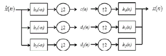
| The DD was consisted of two stages of filter banks as shown in Fig. 1: |
(i)Analysis |
| In the analysis filter banks, three filters were implemented and the original signals were down-sampled by 2 in order to
decompose the signals into three sub-bands. The low frequency sub-band, c(n) was produced by low pass filter h
0
(-n), and the two high frequency sub-bands d
1
(n), and d
2
(n) were
produced by high pass filters h
1
(-n), and h
2
(-n). |
(ii) Synthesis |
| The synthesis filter banks were the inverse of analysis filter banks where the three sub-bands were up-sampled by 2,
filtered by the high pass filter h
0
(n) and the two low pass filters h
1
(-n), and h
2
(-n). The filtered signals were combined to
form the output signal x(n). |
2) Double Density Complex DWT (DDC) |
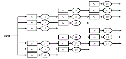
| The input data were processed by two parallel iterated filter banks h
i
(n) and g
i
(n) where i = 0, 1, 2. The real part of a
complex wavelet transform was produced by the sub-band signals of the upper DWT
the imaginary part was produced by the lower DWT |
RESULTS AND DISCUSSION |
| Here examined the NR methods that are linked to turbulence . The measured values are compared with proposed FR
methods (PSNR ,PIM and VSNR) . Hence the chosen metrics are used in estimating the results for turbulence
mitigation in visual surveillance. |
A. Quality Metric Selection |
| The number of image sequences are generated that are distorted by turbulence with various gases flow for different
things, texts ,faces etc. The frame from each sequence is selected and performance checked for the current novel
method. |
B. Results for Setatic Scenes |
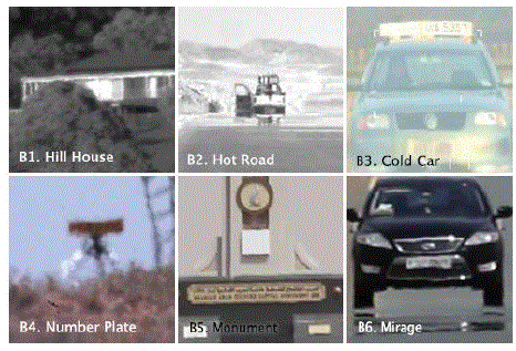
| The other two datasets include real effects of turbulence in long range imaging. These real datasets have been captured
without ground truth (B1–B6) and with ground truth (C1–C3). |
C. Results for Sequences Containing Moving Objects |
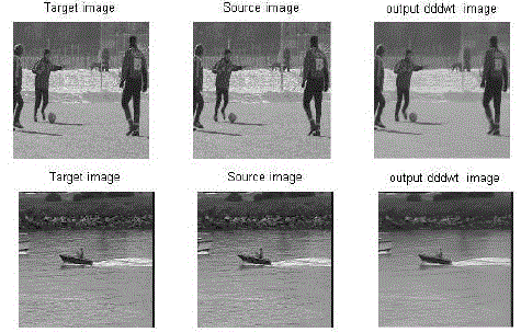
| This section shows the potential of the proposed algorithm when applied to videos containing moving objects. Here,
part of the moving object is manually selected as the ROI. |
CONCLUSION |
| Complex Wavelet Transform to shrink coefficients from the enhanced, noisy image. Always according to data
directionality, the shrunk coefficients are mixed with those from the non-enhanced, noise-free image. The output image
is then computed by inverting the Dual Tree Complex Wavelet Transform and the color transform. In certain signal
processing applications, like de noising, over complete The DD-DWT is expansive with a factor of two, compared to
the critically sampled DWT arrhythmias based on their characteristics features extracted from ECG signals. Intended
for PVC beat exposure RR interval ratio and power of beat is calculated.. The rest of this paper is organized as follows:
presents the ECG signal processing. Describes the detection of arrhythmia. Finally, the summarizes the result &
conclusion of this work. |
Figures at a glance |
 |
 |
 |
 |
| Figure 1 |
Figure 2 |
Figure 3 |
Figure 4 |
 |
 |
 |
 |
| Figure 5 |
Figure 6 |
Figure 7 |
Figure 8 |
|
References |
- L. C. Andrews, R. L. Phillips, C. Y. Hopen, and M. A. Al-Habash, “Theory of optical scintillation,” J. Opt. Soc. Amer. A, vol. 16, no. 6, pp. Jun. 1999.
- H. S. Rana, “Toward generic military imaging adaptive optics,” Proc. SPIE, vol., Sep. 2008.
- Advanced Electro-Optical Systems. (2012) Online]. Available:
- B. Davey, R. Lane, and R. Bates, “Blind de convolution of noisy complex-valued image,” Opt. Commun., vol. 69, nos. 5–6, pp, 1989.
- E. Y. Lam and J. W. Goodman, “Iterative statistical approach to blind imageDe convolution,” J. Opt. Soc. Amer. A, vol. 17, no. 7,pp., Jul. 2000.
- S. Harmeling, M. Hirsch, S. Sra, and B. Scholkopf, “Online blind image deconvolution for astronomy,” in Proc. IEEE Conf., pp. 1–7.
- J. Gilles, T. Dagobert, and C. Franchis, “Atmospheric turbulence restoration by diffeomorphic image registration and blinddeconvolution,” Conf. Adv. Concepts Intell. Vis. Syst., 2008, pp. 400–409.
- C. S. Huebner, “Compensating image degradation due to atmospheric turbulence in. 2009.
- D. Li, “Suppressing atmospheric turbulentmotion in video through trajectory smoothing,” Signal Process.,. 4, pp. 649–655, 2009.
- M. Hirsch, S. Sra, B. Scholkopf, and S.Harmeling, “Efficient filter flow for spacevariantmultiframe blind deconvolution,” in Proc. Comput. Vis. Pattern Recognit., , pp. 607–614.
- J. Delport, “Scintillation mitigation for long-range surveillance video,” in Proc. Sci. Real Relevant Conf., 2010, pp. 1–8.
- X. Zhu and P. Milanfar, “Removing atmospheric turbulence via space invariant deconvolution,” IEEE Trans. Pattern Anal. Mach. Intell., vol. 35, no. 1, pp. 157–170, Jan. 2013.
- N. Joshi and M. Cohen, “Seeing Mt. Rainier: Lucky imaging for multi image De noising, sharpening, and haze removal,” in Proc. IEEE Int. Conf. Comput. Photography, Mar. 2010, pp. 1–8.
- R. Gregory, “A technique of minimizing the effects of atmospheric disturbance on photographic telescopes,” Nature, vol. 203, pp. 274–295, May 1964.
- Z. Wen, D. Fraser, and A. Lambert, “Bicoherence used to predict lucky regions in turbulence affected surveillance,” in Proc. IEEEInt. Conf. Video Signal Based Surveill., Nov. 2006, p. 108.
|