Keywords
|
| Multilevel Inverters, Sinusoidal phase shift carrier PWM, level shift Phase Dispose PWM, Pulse generation, THD analysis. |
INTRODUCTION
|
| Numerous industrial applications have begun to require higher power apparatus in recent years. Some medium voltage motor drives and utility applications require medium voltage and megawatt power level. For a medium voltage grid, it is troublesome to connect only one power semiconductor switch directly. As a result, a multilevel power converter structure has been introduced as an alternative in high power and medium voltage situations. A multilevel converter not only achieves high power ratings, but also enables the use of renewable energy sources. Renewable energy sources such as photovoltaic, wind and fuel cells can be easily interfaced to a multilevel converter system for a high power application [1-3]. |
| The concept of multilevel converters has been introduced since 1975[4]. The term multilevel began with the three level converters [5]. Subsequently, several multilevel converter topologies have been developed [6-13]. However, the elementary concept of a multilevel converter to achieve higher power is to use a series of power semiconductor switches with several lower voltage dc sources to perform the power conversion by synthesizing a stair case voltage waveform. Capacitors, batteries and renewable voltage sources can be used as the multiple dc voltage sources. |
| The cascaded H-bridge five-level multilevel inverter (MLI) has 8 switches. Sinusoidal phase shift carrier PWM used for Cascaded H-ridge five-level MLI, all the switches operated with carrier switching frequency, so the switching losses are high. The same five-level output voltage produced with 6 switches (Multistring five-level MLI), the level shift phase dispose PWM used. In these inverter, the 2 switches operated with fundamental frequency and remaining switches operated with carrier switching frequency, then switching losses are low compared with the Cascaded Hbridge five-level MLI [14]. |
| The PWM techniques used in the MLIs, the switching losses are high and efficiency decreases and the switches capable of carrier switching frequency, the cost of switches are high. |
| In this paper the switches operated with fundamental switching frequency, which the switching losses are decreases and efficiency increases. The switches capable of fundamental switching frequency and then cost of switches are low. A Proposed novel simplified cascaded multistring and H-bridge MLI have 10 switches and three batteries. The proposed novel simplified cascaded multistring and H-bridge MLI produced nine, eleven, thirteen and fifteen level stair case output voltage with only 10 switches. The output voltage level increases corresponding THD decreases. |
| The basic Inverter converts DC into AC at desired output voltage and frequency. The inverter output produces two voltage levels +Vdc and -Vdc. The inverter output produces symmetrical square wave. The square wave output voltage contains infinite number of odd harmonics. The harmonics reduced by using Multilevel Inverters. Multilevel inverter is defined as level refers to the various voltage values in a cycle. The Multilevel inverter starting from three level output voltage. The basic inverter produces three voltage levels 0, +Vdc and -Vdc. The three level output voltage contains the harmonic content reduced compared to the two level output voltage. The voltage levels are increasing, the harmonic content in the output voltage reduces and the easily sine wave output wave form produces from multilevel inverters. |
| A. Cascaded H-bridge Five-level Multilevel Inverter (MLI) |
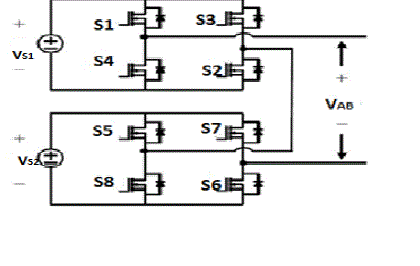
| The One full H-bridge inverter produces three voltage levels. They are 0, +Vdc and -Vdc. The five-level output voltage are producing from two full H-bridge inverters connected in cascaded form. They are 0, +2Vs, +Vs, -2Vs and – Vs. The sinusoidal phase shift carrier pulse width modulation used for cascaded H-bridge five-level inverter. The carrier frequency used for carrier wave 1860Hz. |
| In the Table I shows, „1? means switch is ON and „0? means switch is OFF in the Cascaded H-bridge 5-level MLI. The VS1=VS2=100V as the input voltage of inverter. The sinusoidal phase shift carrier PWM applied to the circuit, which PWM contains one reference waveform and four carrier wave forms. The phase shift of the carrier wave form is 3600/(n-1), the „n? means number of voltage levels. The first carrier wave form operated with 0 degrees, the second carrier wave form shifted with 90degrees, third carrier waveform shifted with 180degress and fourth carrier waveform shifted with 270 degrees. All switches operated with carrier switching frequency, whose switching losses are high in the above circuit. The five level output voltage produced in the above circuit. |
| B. Multistring Five-level multilevel inverter (MLI) with six switches |
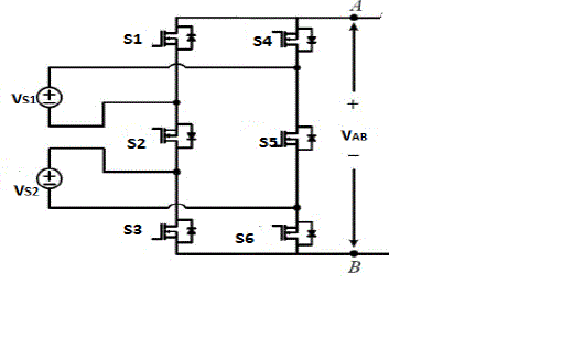
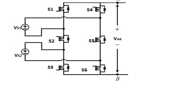
| The five-level output voltage produced by using two sources with six switches. They are 0, +Vdc, -Vdc, +2Vdc and - 2Vdc. The level shift phase dispose pulse width modulation used in the Multistring five-level multilevel inverter with six switches, which compared to the Cascaded H-bridge Five-level Multilevel inverter then switching devices, circuit complexity, area required and also cost reduced. The VS1= VS2= 100V as the input voltage of this inverter.The carrier switching frequency 1860Hz used in the Multistring Five-level MLI for S1, S4, S3 and s6. The fundamental switching frequency used for S2, S5 switches. |
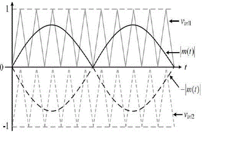
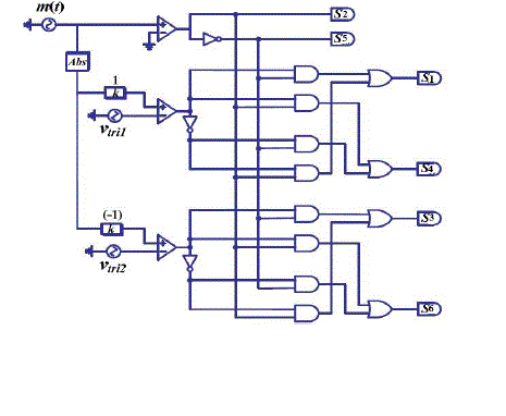
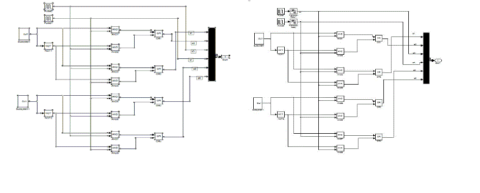
| In the table II shows „1? means switch is „ON? and „0? means switch is „OFF? in the Multistring five-level MLI diagram. In the above Fig.2 shown operated with level shift phase dispose PWM, which PWM contains two reference wave forms and two carrier waveforms in the Fig.3 shown and modulation logic of Multistring 5-level MLI in the Fig 4 shown. The above Fig.4 shown the middle switches operated with fundamental switching frequency (S2, S5) and remaining four switches operated with switching carrier frequency (S1, S3, S4, S6) of modulation logic applied to the multistring 5-level MLI (Fig.2 shown) compared to 5-level cascaded H-bridge MLI have one reference wave form and four carrier wave forms then switching losses are high in the cascaded H-bridge 5-level MLI. |
| The switching losses decreases in the multistring 5-level MLI compared to the Cascaded H-bridge 5-level MLI. |
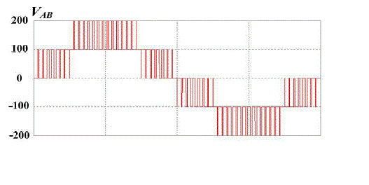
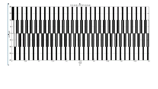
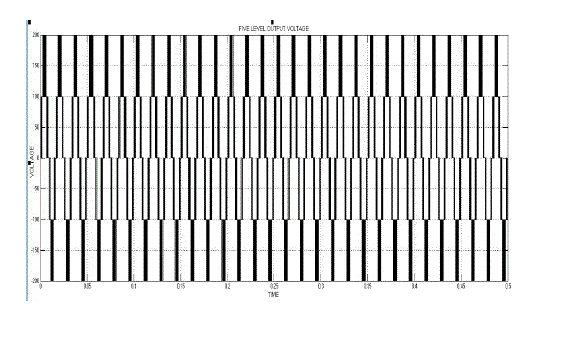
| The above Fig.5 is shown 5-level output voltage of 5-level multistring MLI. The same output voltage of 5-level cascaded H-bridge MLI. |
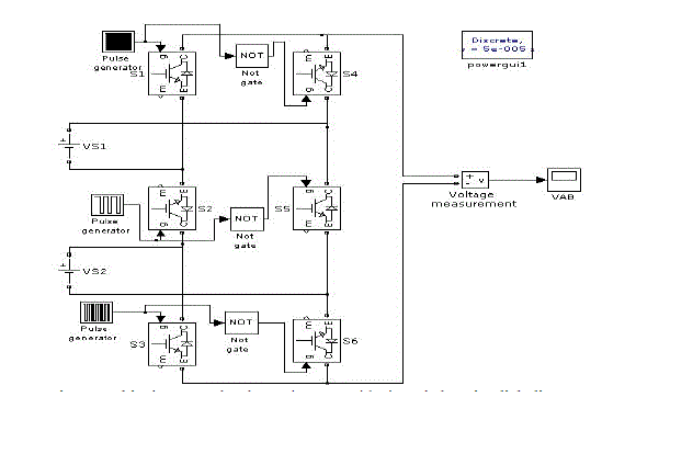
| The above table III shows comparison between the Cascaded H-bridge MLI and Multistring MLI. The PWM techniques used for MLIs, the switching losses are high. The cost is high because PWM techniques used in the MLI (the switches capable of carrier switching frequency, so the cost of switches are high). The seven level output voltage produced with same number of (six) switches of Multistring MLI. As the switches operated with fundamental switching frequency, the cost of switches is low. So, the switching losses are low and reduce the number of switches (compared to cascaded H-bridge configuration of 12 switches require to produce seven level), complexity and control circuit. The Multistring seven level MLI operation is shown below. |
| C. Multistring seven-level multilevel inverter (MLI) with six switches |
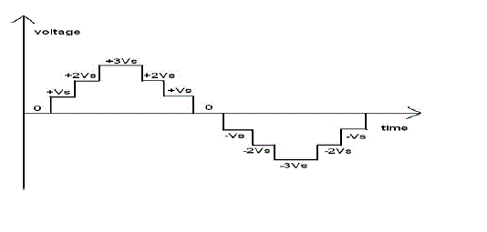
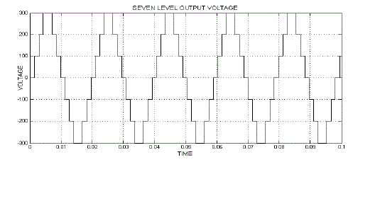
| In the above Fig.6 shown, 7-level output voltage produced from multistring 7-level MLI with six switches. Generally the cascaded H-bridge configuration the 7-level output voltage is produced by using 12 switches. But the seven level output voltage produced by using six switches. In the table IV shows the switching sequence „1? means switch is „ON? and „0? means switch is „OFF? in the 7-level inverter with 6 switches (above Fig 6 shown). The six switches operated with fundamental switching frequency. The switching losses decreases compared to the above two MLIs. |
PROPOSING SYSTEM OF A NOVEL SIMPLIFIED CASCADED MULTISTRING AND H-BRIDGE MULTILEVEL INVERTER
|
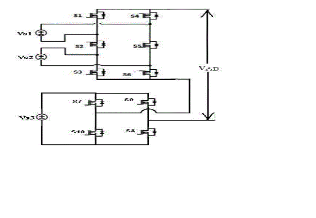
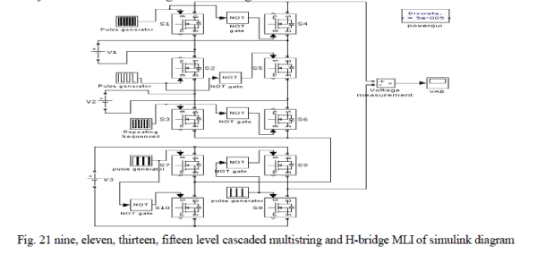
| In the above circuit Fig.8 has shown three batteries and ten switches. In this circuit, all switches operated with fundamental switching frequency. A novel simplified cascaded multistring and H-bridge multilevel inverter produces nine, eleven, thirteen and fifteen level output voltage levels. In cascaded H-bridge MLI configuration nine, eleven, thirteen and fifteen level output voltage corresponding switches are 16, 20, 24 and 28 switches. So, nine, eleven, thirteen and fifteen level output voltage levels produced from only ten switches. The novel simplified cascaded multistring and H-bridge MLI operated by pulse generation of nine, eleven, thirteen, fifteen level output voltage. So switching losses decreases and reduces the cost, number of switches, area required, complexity, protection circuit and driving circuit and finally the THD reduces corresponding voltage levels increases and also the switches operated with fundamental switching frequency (pulse generation). |
| A. Nine Level cascaded multistring and H-bridge MLI |
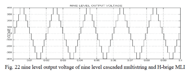
| In the above circuit shown (Fig.8), the input voltage V1=100V, V2=200V and V3=100V taken. The output voltage levels are +4VS, +3VS, +2VS, +VS, 0, -VS, -2VS, -3VS, -4VS.The nine level output voltage produced in the cascaded multistring and H-bridge multilevel inverter is called as Nine level cascaded multistring and H-bridge MLI. The all switches operated with fundamental frequency. Generally, the nine level output voltage produce with 16 switches in cascaded form but we obtained nine level output voltage by only ten switches. The nine level output voltage with switching sequence of 10 switches table V shows below. In the table „1? means switch is „ON? and „0?means switch is „OFF?. |
| B. Eleven Level cascaded multistring and H-bridge MLI |
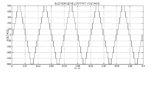
| In the above circuit shown (Fig.8), the input voltage V1=100V, V2=200V and V3=200V taken. The output voltage levels are +5VS, +4VS, +3VS, +2VS, +VS, 0,-VS,-2VS,-3VS,-4VS,-5VS. The eleven level output voltage produced in the cascaded multistring and H-bridge MLI is called as Eleven level cascaded multistring and H-bridge MLI. The all switches operated with fundamental switching frequency. Generally, the eleven level output voltage produce by 20 switches in cascaded form but we obtained eleven level output voltage with only ten switches. The eleven level output voltage with switching sequence 10 switches table VI shown below. In the table „1? means switch is „ON? and „0? means switch is „OFF?. |
| C. Thirteen Level cascaded multistring and H-bridge MLI |
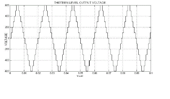
| In the above circuit shown (Fig.8), the input voltage V1=100V, V2=200V and V3=300V taken. The output voltage levels are +6VS, +5VS, +4VS, +3VS, +2VS, +VS, 0, -VS, -2VS, -3VS, -4VS, -5VS, -6VS. The thirteen level output voltage produced in the cascaded multistring and H-bridge MLI is called as Thirteen level cascaded multistring and H-bridge MLI. The all switches operated with fundamental switching frequency. Generally, the thirteen level output voltage produce with 24 switches in cascaded form but we obtained thirteen level output voltage by only ten switches. The thirteen level output voltage with switching sequence 10 switches table 7 shown below. In table „1? means switch is „ON? and „0? means switch is „OFF?. |
| D. Fifteen Level cascaded multistring and H-bridge MLI |
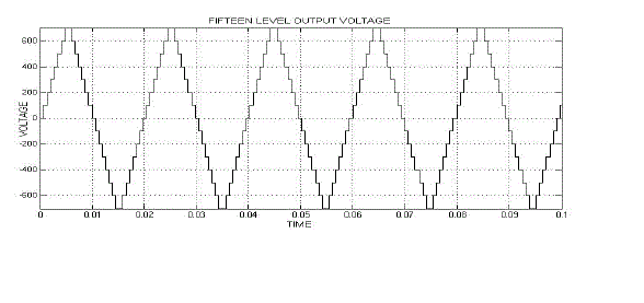
| In the above circuit shown (Fig.8), the input voltage V1=100V, V2=200V and V3=400V taken. The output voltage levels are +7Vs, +6VS, +5VS, +4VS, +3VS, +2VS, +VS, 0, -VS, -2VS, -3VS, -4VS, -5VS, -6VS, -7Vs. The fifteen level output voltage produced in the cascaded multistring and H-bridge MLI is called as Fifteen level cascaded multistring and H-bridge MLI. The all switches operated with fundamental switching frequency. Generally, the fifteen level output voltage produce with 24 switches in cascaded form but we obtained fifteen level output voltage by only ten switches. The fifteen level output voltage with switching sequence 10 switches table VIII shown below. In table „1? means switch is „ON? and „0? means switch is „OFF?. |
| E. Different Voltages are taken as the source voltages of the cascaded multistring and H-bridge MLI |
| The nine, eleven, thirteen and fifteen levels output voltage got only from ten switches corresponding to respective voltage sources taken. The above table 9 shows different voltages are taken for cascaded multistring and H-bridge MLI. The cascaded multistring and H-bridge MLI are simulated the different output voltage levels used by the table IX. |
MATLAB/SIMULATION RESULTS
|
| A. Cascaded H-bridge Five-level MLI |
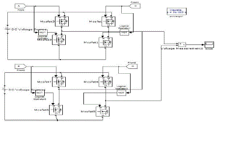
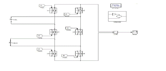
| The simulation diagram for cascaded H-bridge five level inverter diagram as shown above. |
| B. Multistring Five-level MLI |
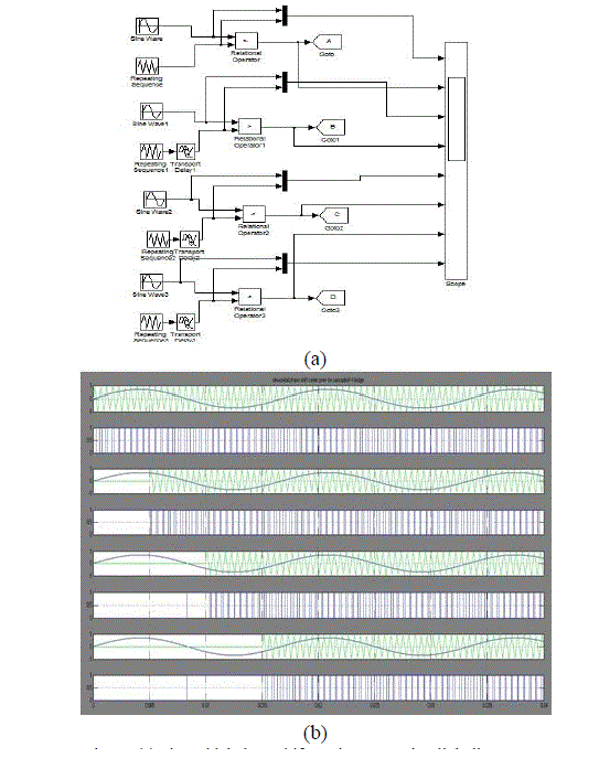
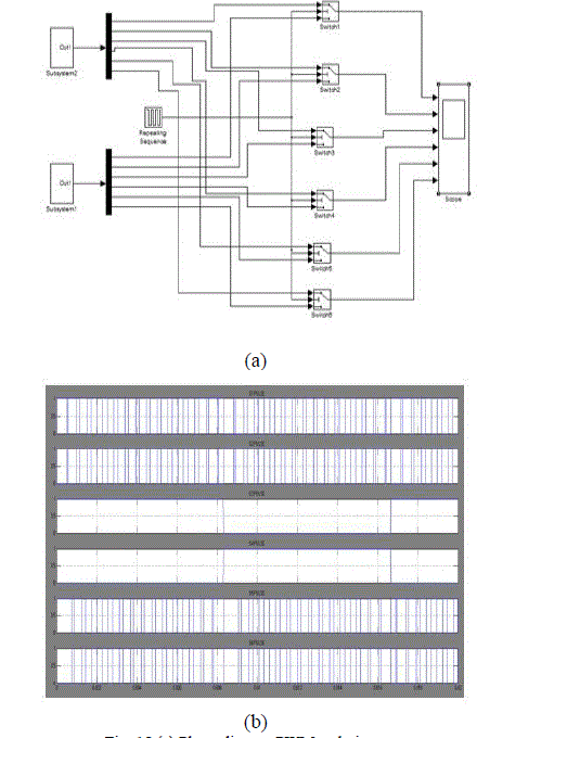
| The above Fig 14(a) is shown subsystem2 of phase dispose PWM technique (Fig.15) and Fig.14 (b) shown subsystem1 of phase dispose PWM technique (Fig.15). |
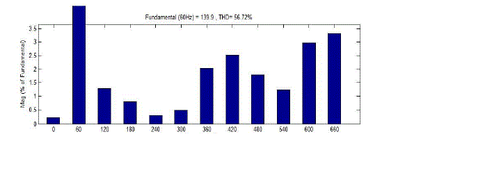
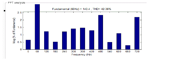
| The PWM techniques used in the Cascaded H-bridge five-level MLI and Multistring Five level MLI simulated as shown above. The THD value low (42.36%) in the multistring five levels MLI compared with the Cascaded H-bridge five-level MLI (56.72%). |
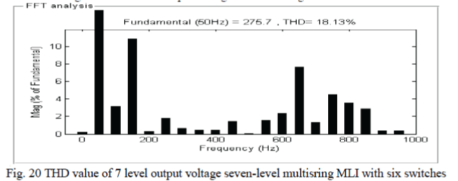
| The switching losses are high, cost of switches high and efficiency decreases in the PWM techniques used for above two five level MLIs. The seven level output voltage produced with same number of switches (six) Multistring MLI as shown below. All the switches operated with fundamental switching frequency then switching losses decreases and efficiency increases. |
| C. Multistring 7-level MLI with six switches |
| D. Proposing system of cascaded multistring and H-bridge MLI |
| 1) Nine level cascaded multistring and H-bridge MLI |
| 2) Eleven level cascaded multistring and H-bridge MLI |
| 3) Thirteen level cascaded multistring and H-bridge MLI |
| 4) Fifteen level cascaded multistring and H-bridge MLI |
| In the above table X shows compare between Cascaded H-bridge MLI and Proposed Cascaded Multistring And HBridge MLI, the switches in the cascaded form increases when increasing the output voltage levels. The cost of switches, reduce the number of switches, protection circuit, cooling equipment, control circuit increases in the cascaded form. But the Proposed Cascaded Multistring and H-Bridge MLI produced higher output voltage levels are 9, 11, 13, 15 level with ten switches only. So, the cost of switches reduce the number of switches, protection circuit, cooling equipment, control circuit decreases compared to the Cascaded H-bridge MLI. |
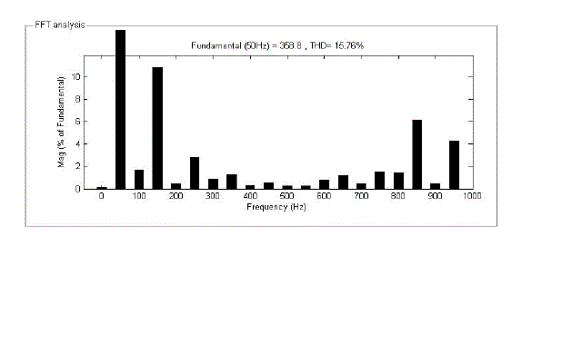
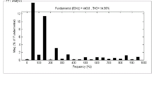
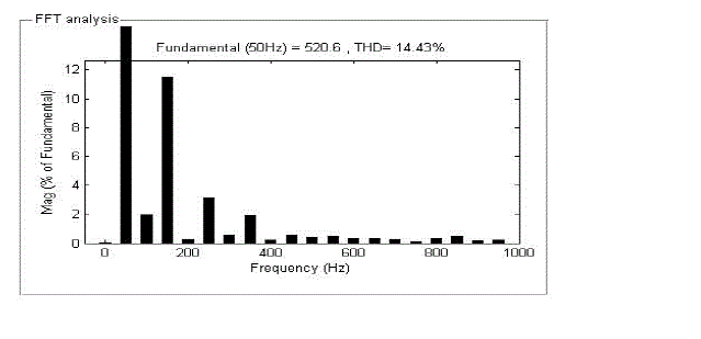
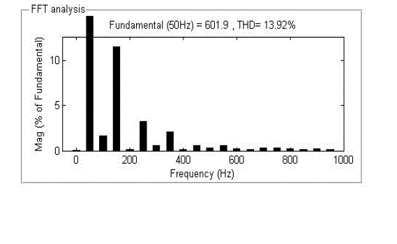
| In the above table shows the output voltage increases corresponding to the THD value decreases in the proposed cascaded multistring and H-bridge multilevel inverter from 9 levels to 15 voltage levels. |
CONCLUSION
|
| In this paper “A Novel simplified Cascaded Multistring and H-Bridge MLI” produced higher output voltage level consisting of nine, eleven, thirteen, fifteen voltage levels. The THD value decreases, when increasing higher output voltage levels and also reduce the number of switches, cost, area required, protection circuit, cooling equipment, and driving circuit and also switching losses decreases, efficiency increases. |
| The Cascaded Multistring and H-Bridge MLI are easily interfaced with DERs. They are photovoltaic arrays and fuel cells. |
Tables at a glance
|
 |
 |
 |
 |
| Table 1 |
Table 2 |
Table 3 |
Table 4 |
 |
 |
 |
 |
| Table 5 |
Table 6 |
Table 7 |
Table 8 |
 |
 |
 |
| Table 9 |
Table 10 |
Table 11 |
|
| |
Figures at a glance
|
 |
 |
 |
 |
 |
| Figure 1 |
Figure 2 |
Figure 3 |
Figure 4 |
Figure 5 |
 |
 |
 |
 |
 |
| Figure 6 |
Figure 7 |
Figure 8 |
Figure 9 |
Figure 10 |
 |
 |
 |
 |
 |
| Figure 11 |
Figure 12 |
Figure 13 |
Figure 14 |
Figure 15 |
 |
 |
 |
 |
 |
| Figure 16 |
Figure 17 |
Figure 18 |
Figure 19 |
Figure 20 |
 |
 |
 |
 |
 |
| Figure 21 |
Figure 22 |
Figure 23 |
Figure 24 |
Figure 25 |
 |
 |
 |
 |
| Figure 26 |
Figure 27 |
Figure 28 |
Figure 29 |
|
| |
References
|
- J.Rodriguez, J.s. Lai and F.Z. Peng, “Multilevel Inverters: Survey of Topologies, Controls and Applications” IEEE Transactions on Industry Applications, vol. 49, no.4, PP.724-738, Aug. 2002.
- J.S.Lai and F.Z. Peng, “Multilevel Converters-A new Breed of Power Converters”, IEEE Trans. Ind Applications, vol.32.pp. 509-517, May/June 1996.
- L. M. Tolbert, F.Z. Peng and T. Habetler, “Multilevel Converters for Large Electric drives”, IEEE Transaction Industrial Applications, vol.35, pp. 36-44, jan/Feb.1999.
- R.H. Baker and L. H. Bannister, “Electric Power Converter?, U.S. Patent3 867 543, Feb. 1975.
- A. Nabae, I. Takahashi and H. Akagi, “A New Neutral-point clamped PWM inverter”, IEEE Trans. Ind. Applicat. Vol. IA-17, pp. 518-523, Sept/Oct. 1981.
- R.H. Baker, “Bridge Converter circuit”, U.S. Patent 4 270 163, May 1981.
- P.W. Hammond, „Medium voltage PWM Drive and Method”, U.S. Patent 5 625 545,Apr .1977.
- F.Z. Peng and J.S. Lai, “Multilevel Cascade voltage-source Inverter with DC source”, U.S. Patent 5 642 275 June 24, 1997.
- P.W. Hammond, “Four-quadrant AC-AC Drive and Method”, U.S. Patent 6 166 513, Dec. 2000.
- M. F. Aiello, P.W. Hammond and M. Rastogi, “Modular Multi-level Adjustable Supply with Series Connected Active Inputs”,U.S patent 6 236 580, May 2001.
- M.F.Aiello, P.W. Hammond and M. Rastogi, “Modular Multi-Level Adjustable Supply with Parallel Conneced Active Inputs”, U.S.Patent6 301 130, Oct.2001.
- J.P. Lavieville, P.Carrere and T.Meynard, “Electronic ciruit for Converting Electrical Energy and a power supply Installation Making use of thereof”, U.S. Patent 5 668 711 Sept. 1997.
- T.Meynard, J.P. Lavieville, P.Carrere, J.Gonzalez and O. Bethoux, “Electronic circuit for converting Electrical Energy”, U. S patent 5 706 188, Jan 1998.
- Yi-Hung Liao, Member, IEEE and Ching-Ming Lai, Member, IEEE “Newly-Constructed Simplified Single-Phase Multistring Multilevel Inverter Topology for DistributedEnergy Resources”,PP. 1-6 ,2011.
|