Keywords
|
| five phase BLDC Motor, microcontroller, hall sensor, PI Controller |
INTRODUCTION
|
| BLDC Motors supersede traditional commutator motors due to their superior efficiency, long life, smooth torque delivery, and high speed operation. Instead of mechanical brushes and commutator, the brushless DC motor uses electronic commutator. This enormously improves the reliability of the system over brushed DC motors. In addition, it reduces the system maintenance cost, and creates clean and safer working system environment. Hence they are widely used in robotics, automotive, aerospace, medical equipment, home appliances, computer peripherals and so on [1]. Three-phase drive systems have been widely used for years because of the availability of such machines, their inverters, modelling and control. However, multiphase drives are likely to be limited to specialized applications where high performance and reliability are required (such as EV, HEV, aerospace, ship propulsion and high power applications) and when cost requirements are not so oppressive when compared to the overall environment. |
| A multi-phase machine is a system with numerous numbers of windings i.e they have many degrees of freedom that can be used for many purposes such as power density improvement, monitoring and so on. With the advancements in power electronics, multi-phase inverters with high power electronic devices as switches can supply power to multiphase machines. Each leg of the multi-phase inverter represents the phase. As the number of phase increases current per phase is reduced without causing any change to voltage, reduce torque pulsation and increased pulsating frequency, lower the dc- link current harmonics, reduce the stator copper loss, increase power output per frame, increase reliability as it can continue its operation even one or two phases are opened. Additional degrees of freedom in multi-phase machines are employed to improve the fault-tolerant capability, thereby the overall performance of the system. Also, the presence of more space voltage vectors, allows better adjustment of torque and flux in a direct torque controlled system [2]. |
| High performance motor drives with good dynamic speed command tracking and load regulating response play a major role in many of the industrial applications. For example in aerospace, there are a number of applications, like centrifuges, pumps, robotic arm controls, gyroscope controls and so on. These applications use advanced control algorithms and may use speed feedback devices [3]. In recent years, digital control systems are continuing to replace classical analog control by using fast numerical computing digital microprocessors and microcontrollers [4]. The rotor speed can be determined using an external rotary encoder or a tachometer. Another alternative is based on an estimation of the period of a rotor position sensor. The above mentioned methods are expensive and sometimes not feasible due to size problem. This paper describes a simple and feasible speed measurement method on a 16 bit microcontroller platform for a five phase BLDC Motor. A PI speed controller is also implemented with the proposed speed measurement method in the feedback circuit. The controller alters the average voltage applied on the motor windings by adjusting the duty cycle of the PWM signals which brings the motor speed to the desired level. |
PROPOSED FIVE PHASE BLDC MOTOR DRIVE
|
| A. Theory of Operation |
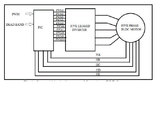
| A five-phase BLDC motor has ten states of commutation and is hence fed from a five legged inverter. Rotating field is created by trapezoidal commutation and it is necessary to keep the angle between stator and rotor close to 900 for the motor to operate properly. The control block diagram of five phase BLDC motor is shown in fig.1. BLDC motor control system mainly comprises of DC voltage source, power electronics inverter, motor, rotor position sensor, and digital controller. The rotor position information, which is sensed using Hall Effect sensors embedded into the stator on the non-driving end of the motor, is used to perform electronic commutations. Whenever the rotor magnetic poles pass near the Hall sensors, they give a high or low signal, indicating the N or S pole is passing near the sensors. The commutation sequence is implemented in software using microcontroller. Table 1 shows the hall sensor pattern and the motor phase windings to be energised in the ten step commutation. |
| B. Five Phase Inverter |
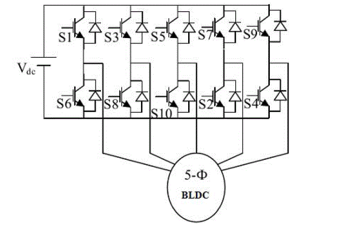
| Five phase BLDC motor drive contains a five-leg inverter. In this converter four switches are conducting at a time. That is two from the upper group of switches and two from the lower group of switches. No two switches of the same leg are allowed to conduct at the same time. If for example transistor S1 and S6 were allowed to conduct at the same time, the circuit will be short-circuited, this is referred to as shoot-through, and this will in general destroy the transistors. In the fig.2 S1, S3, S5, S7 and S9 indicates the upper group of switches and S2, S4, S6, S8 and S10 indicates the lower group of switches. To rotate the five phase BLDC motor any of its two stator winding has to be energized with positive power, other two windings with negative (current flows out of winding) and one with nonenergized condition in a particular sequence. To prevent shoot-through while commutation, a dead-time delay has to be inserted between turnings off the transistors that were active and turning on those who are supposed to become active. |
PROPOSED SPEED MEASUREMENT METHOD FOR BLDC MOTOR
|
| In many drive systems, motion control is a fundamental subject and hence fast and accurate speed measurement is of great importance for high performance control. There are different devices as well as technologies developed for the speed measurement of BLDC motor. Optical methods, mechanical and optical tachometers, shat encoders, image based, mechanical and magnetic systems are few examples. Among them, magnetic sensors built with Hall-Effect sensors not only have small size and low cost advantages, but also offer relatively impressive performance in RPM determining applications. Therefore, they appear to be the most promising one of all the available technologies in terms of tiny, selfcontained, complete, accurate, fast, robust immune to occlusions, tenacious, and cheap [5]. |
| There are two methods of determining RPM: The Frequency measurement method and the Period measurement method. Frequency measurement is better for fast-moving devices such as motors and turbines that typically turn in thousands of revolutions per minute. Period measurement is better for devices that move more slowly, such as shafts that turn in less than 10 RPM. The RPM measurement equation using frequency measurement method is given as: |
 |
| When using period measurement to monitor RPM, calculate the RPM using this equation: |
 |
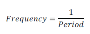
| Period is the time from the start of one pulse to the start of the next pulse. The relationship between frequency and period: |
 |
| For motors with multiple poles, the electrical rotation does not correspond to a mechanical rotation. A four-pole BLDC Motor uses two electrical rotation cycles to per mechanical rotation. Hence the RPM measured by the above equations has to be divided by the number of poles of the motor in order to obtain the actual RPM. |
| In this paper, the speed of BLDC motor is measured by frequency measurement of the hall sensor output and is done using a 16-bit microcontroller. This is accomplished by utilizing a counter in the microcontroller that counts the signals from one of the position sensors. The counter is cleared in a timer interrupt service routine configured for one second duration of time. Before the counter reset, the count result is copied to a register, the value of which corresponds to the electrical rotation of the motor per second. This electrical rotation is multiplied by sixty and divided by the number of poles of the motor to give the speed of the motor in RPM. The sensor pulse per revolution for BLDC motor is one. This is a simple speed measurement method with good accuracy. Since the method is implemented in digital domain, complexity is incorporated in software rather than in hardware. The drawbacks of analog implementation such as component ageing, sensitive to temperature variations, difficulty in accurately transmitting analog signals and drifts and offset of analog components have been overcome. No extra peripherals other than a programmable timer pin are required for speed measurement. The rotational speed value determined in such a way may then be used as a feedback signal in the speed control system. |
DIGITAL IMPLEMENTATION OF SPEED CONTROL OF BLDC MOTOR
|
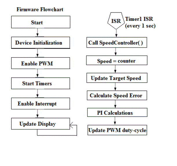
| Speed control of BLDC Motor involves changing the applied voltage across the motor phases, thereby rotating the motor at a constant speed as demanded by the speed command. The most common way to alter the voltages and currents is to use a Pulse-Width Modulated signal. The difference between the required and actual speeds is input to the speed controller which then, based on this difference, controls the duty cycle of the PWM pulses corresponding to the voltage amplitude required to maintain the desired speed. If the error speed is positive, this means the motor is running slow so that the controller output should be increased and vice-versa. The most suitable controller for speed control is PI type controller. Fast-acting correction is done by proportional term which will produce a change in the output as quickly as the error arises. The integral action takes a finite time to act but has the capability to make the steady-state speed error zero.Fig.3 shows the speed control block diagram and fig.4 shows the flowchart of the digital speed controller algorithm. The speed controller calculates the Proportional-Integral (PI) algorithm in discrete domain according to the following equations: |
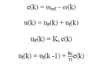 |
| where Kc is controller gain and TI is integral time constant. |
EXPERIMENTAL RESULTS
|
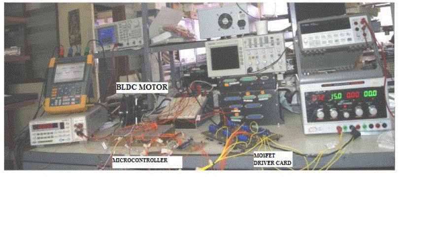
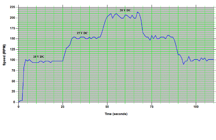
| The experimental setup for proposed five phase BLDC motor drive speed control using PIC24HJ128GP310 microcontroller has been developed as shown in fig 5. PIC24HJ128GP310 microcontroller employs a powerful 16-bit architecture, ideal for applications that rely on high-speed, repetitive computations, as well as control. It is suitable for a wide variety of high performance digital signal control applications. The proposed BLDC motor contains sixteen poles and five phases. The inductance and resistance of each phase is 0.7mH and 4.5ohm respectively. Five Hall sensors are used for sensing rotor position. The hall sensor used in this motor is A3187LUA. The sensors are energized from a separate source of 5V. A ten step commutation sequence is generated to rotate the motor. The PWM signals from microcontroller are given to five phase voltage source inverter through a matching driver circuit. The switching frequency is 10KHz.The PWM duty cycle is adjusted to control the average voltage across the winding and hence the speed is controlled. The speed is measured and verified with a fixed PWM duty cycle of 80% for 10V, 15V, 20V supply voltages as shown in fig 6. The measured speed and current drawn are represented in Table II which indicates that the proposed speed measurement method is actually feasible with good accuracy. |
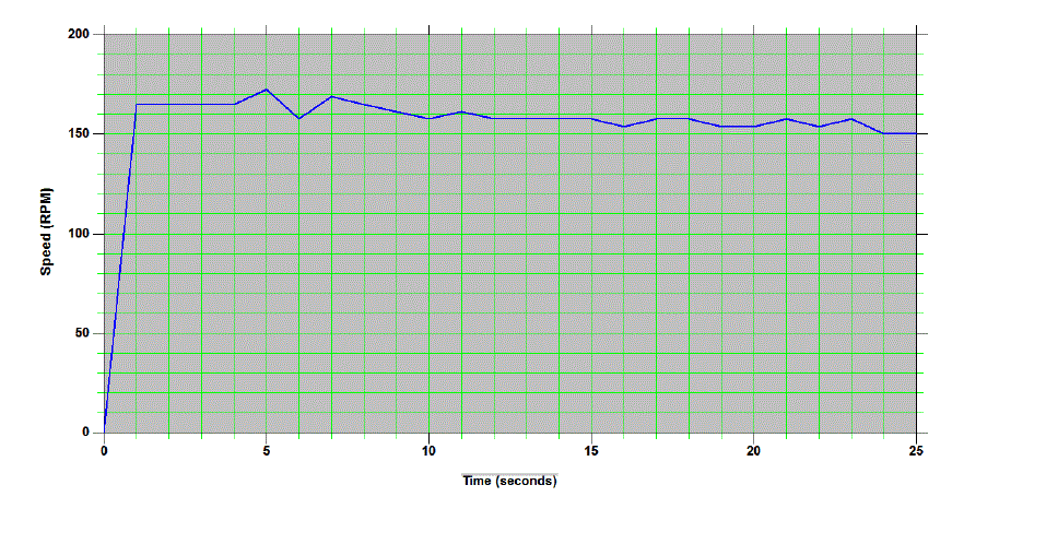
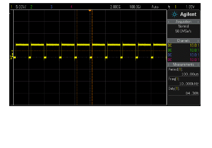
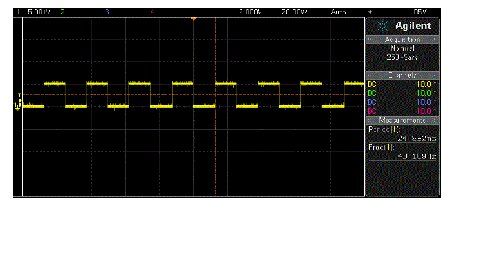
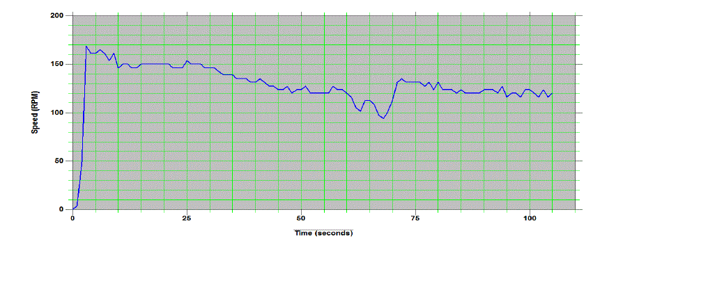
| The speed control scheme is then verified. The controller gain is taken as 1. The reference speed value from PC is set in the microcontroller using RS232 communication protocol and UART. The error in the set speed and actual speed is calculated. A digital Proportional plus Integral controller is used to amplify this speed error and dynamically adjust the PWM duty cycle. The DC supply voltage is 15V. Fig.7 shows the speed response versus time for a set speed of 150RPM under no load condition. Fig.8 and Fig.9 show the PWM output and Hall sensor output for 150RPM reference speed respectively. |
CONCLUSION
|
| The paper describes a novel speed measurement technique and speed control for BLDC Motor using a high speed 16- bit microcontroller. The proposed speed measurement technique was experimented on a five phase BLDC Motor drive fed from a five phase voltage source inverter. Furthermore the closed loop speed control using a digital PI controller is also accomplished. The described implementation ensures dynamic speed measurement and control under load with good accuracy. The average error is well less than 5% which can be further reduced with fine tuning of controller. Since the control algorithm is completely implemented in software, there is simplification of hardware and construction cost. The frequency of any one of the hall sensors which is required for sensing rotor position is measured and it does not require any additional sensors, a rotary encoder or a tachometer. This is a simple technique where no further conversion or sampling is required. The results show that the proposed method is actually feasible. |
Tables at a glance
|
 |
 |
| Table 1 |
Table 2 |
|
| |
Figures at a glance
|
 |
 |
 |
 |
| Figure 1 |
Figure 2 |
Figure 3 |
Figure 4 |
 |
 |
 |
 |
| Figure 5 |
Figure 6 |
Figure 7 |
Figure 8 |
 |
 |
 |
| Figure 9 |
Figure 10 |
Figure 11 |
|
| |
References
|
- Leila Parsa, Hamid A Toliyat , “Five phase permanent magnet motor drives." IEEE Transactions on industrial applications, Vol 41, No.1. January/February 2005.
- M. Godoy Simões , P. Vieira Jr., “A Five-Phase Brushless DC-Machine Direct Drive System”. EPE Journal Vol. 14 no 3 August 2004 .
- Padmaraja yedamale, “ Brushles DC (BLDC) motor fundamentals” , AN885, microchip technology, 2003
- Anand Sathyan, Nikola Milivojevic, Young-Joo Lee, Mahesh Krishnamurthy and Ali Emadi, “An FPGA-Based Novel Digital PWM ControlScheme for BLDC Motor Drives”, IEEE Transactions on industrial electronics, Vol 56, No.8. August, 2009.
- Mohammad Kia, Kaveh Razzaghi Rezayieh, and Reza Taherkhani, “A Novel Method for Measuring Rotational Speed of BLDC Motors UsingVoltage Feedback ” in 2nd International Conference on Control, Instrumentation and Automation ICCIA,2011,pp.791-794.
|