This paper presents the design and development of slot loaded circular microstrip antenna for penta band operation. Thepenta band antenna has been realised by incorporating plus type equal arm length slots at the centre of the conventional circular microstrip antenna. The proposed antenna is operating between the frequencies range from 2.57 GHz to 11.09 GHz, covering the application bands of WLAN and WiMAX. The antenna gives broadside radiation characteristics at each operating band. The presented antennas are simulated and are analysed using commercial electromagnetic (EM) HFSS simulation software. The experimental and simulation results are given and are discussed in this paper. A close agreement is obtained between the simulated and experimental results.
Keywords |
| Circular microstrip antenna, penta band operation, PTCMSA, WLAN, WiMAX. |
INTRODUCTION |
| Microstrip antennas (MSAs) are occurred in the early 1970s and since then the continuousof research activities in this
area is going on rigorously. The MSAs have well-known advantages over other microwave antenna structures such as
simple to construct, lightweight, inexpensive, low-profile, conformal to the surface, low cost of fabrication,
compatibility with monolithic integrated circuits (MMICs) and optoelectronic integrated circuits (OEICs) technologies
[1] etc. |
| The growing of rapid advances in the modern wireless communication sectors demands the design and development of
antenna that could be used for more than one operating frequency bands with compact in physical size. The Wireless
Local Area Network (WLAN)and Worldwide Interoperability for Microwave Access (WiMAX)technologies need
multi frequency operations. Thus, the multiband antennas are more attractive for modern wireless communications,
because a single device can operates for various frequency bands. Several researchers have published the dual, triple
and quad band antennas and are reported in [2-6]. Introducing L- shaped slot in circular disk patch is presented in [2]
which can operate at two resonance frequencies for 5.087 and 8.445 GHz and useful for dual band operation. Recently,
reported a novel coplanar waveguide (CPW)-fed monopole antenna with simple structure and compact in size suitable
for 2.4 and 5 GHz WLAN systems [3]. A novel design of a simple microstrip-fed monopole is proposed in [4] which
cover WLAN/WiMAX triple-band operations. Multiband printed and double-sided dipole antenna is proposed in [5]
for WLAN/WiMAX applications using a 50-Ω coaxial cable through a microstrip-to-twinline tapered transition. A
compact single-feed planar antenna with three wide 2 : 1 VSWR operating bands around 1.8, 2.4 and 5.8 GHz
covering four useful frequency bands, namely Global Positioning System(GPS: 1575.4 MHz), Digital Cellular
Service(DCS:1800 MHz), 2.4 GHz (2400–2485 MHz) and 5.8 GHz (5725–5825 MHz) WLAN is presented in [6].The
modified penta-band two-strip monopole antenna using thicker substrate is discussed in [7] which areused for Wireless
Fidelity (WiFi) and WiMAXapplications.However, a simple slot loaded circular microstrip antenna fed by 50-Ω
microstripline technique capable to operate for penta frequency bands useful for WLAN and WiMAX applications is
found to be rare in the literature. |
DESIGNING OF ANTENNA CONFIGURATIONS |
| The proposed antennas are printed on low cost modified glass epoxy substrate material of thickness 0.16 cm and a
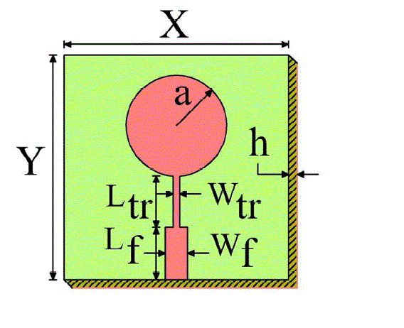
dielectric constant of 4.2. The Fig.1 shows the top view configuration of the conventional circular microstrip antenna
(CCMSA). The CCMSA has been designed for the resonating frequency of 3 GHz. The CCMSA consists of a circular
patch of radius ‘a’ which equal to 1.361 cm. The antenna is fed through a simple 50-Ω microstripline with dimensions
Wf× Lf. The quarter wavelength transformer is used for matching the impedance between the radiating patch and the
50-Ω microstripline with dimensions Wtr× Ltr. The bottom surface of CCMSA is tight copper shielding. |
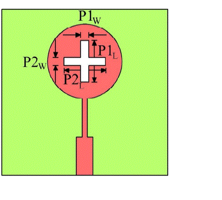
| Figure 2 shows the top view configuration of plus type circular microstrip antenna (PTCMSA). It is formed from
CCMSA by etching plus type slots of equal arm at the centre of the circular radiating patch. The slot dimensions of
PTCMSA are taken in terms of free space wavelength λ0. The dimensions width of two rectangular slots are P1W and
P2W which are equal to λ0/50 (i.e. 0.2cm) and length of two rectangular slots are P1L and P2L which are equal to λ0/7.34
(i.e. 1.361cm). |
| The actual radius of the circular radiating patch is calculated by using the equation [8], |
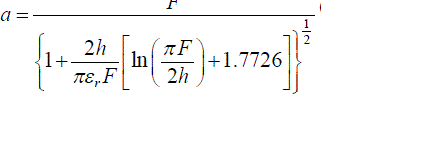 (1) (1) |
| where, |
 |
| Thus the effective area of the circular radiating patch is given by, |
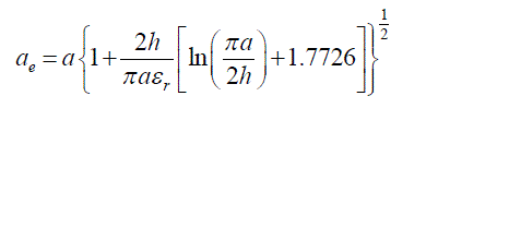 (2) (2) |
| The designed parameters of proposed antennas are shown in Table –I. |
| The schematics of CCMSA and PTCMSA antennas for the fabrication process are outlined using AutoCAD tool
toachieve better accuracy. A 50-Ω semi miniature-A (SMA) connector is used at the tip of the microstripline to feed the
microwave power. |
EXPERIMENTAL RESULTS AND DISCUSSION |
| The parameters of proposed antennas are measured on Vector Network Analyser (Rohde and Schwartz Germany make
ZVK model). The equation used for calculating the impedance bandwidth is, |
 |
| where, fH and fL are the higher and lower cut-off frequency of the band respectively when its return loss becomes -
10dB and fC is the centre frequency between fH and fL . These antennas are also simulated using 3D full wave
electromagnetic (EM) Ansys HFSS simulation software. |
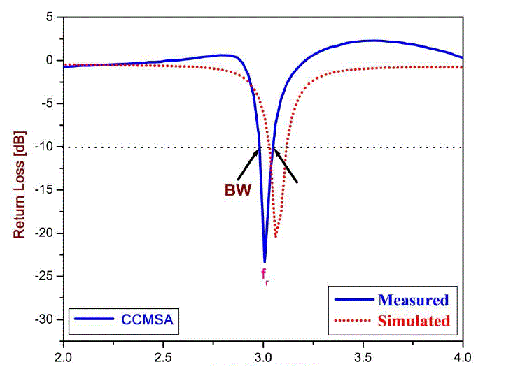
| Figure 3 shows the variation of return loss versus frequency of CCMSA. From this figure it is clear that, the antenna
resonates at 3 GHz (i.e. fr), which is exactly equal to the design frequency of 3 GHz. The impedance bandwidth BW of
CCMSA is found to be 2%. The HFSS simulated result of CCMSA is also illustrated in Fig. 3. A good agreement is
obtained between simulation and experimental results. |
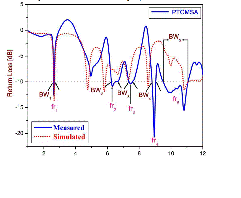
| The variation of return loss versus frequency of PTCMSA is as shown in Fig. 4. From this figure it is observed that, the
antenna is resonating for five resonant modes at fr1, fr2, fr3, fr4and fr5 with a corresponding impedance bandwidths of
BW1= 2.66% (2.59 GHz-2.66 GHz), BW2= 7.14% (6.24 GHz-6.69 GHz), BW3= 3.35% (7.34 GHz-7.59 GHz), BW4=
2.71% (8.80 GHz-9.04 GHz) and BW5= 15.67% (9.51 GHz -11.09 GHz) respectively. Hence by the construction of
PTCMSA from CCMSA the operating frequency modes fr1 to fr5 is possible. It is also seen from this figure that, the
highest impedance bandwidth of 15.67% is found at BW5. The simulated variation of return loss versus frequency
result is also illustrated in the Fig. 4. Hence the use of plus shaped slot on the circular patch is effective in producing
the multiband operation of an antenna. However the dimension of slots may possible to vary to control the operating
bands of the antenna. |
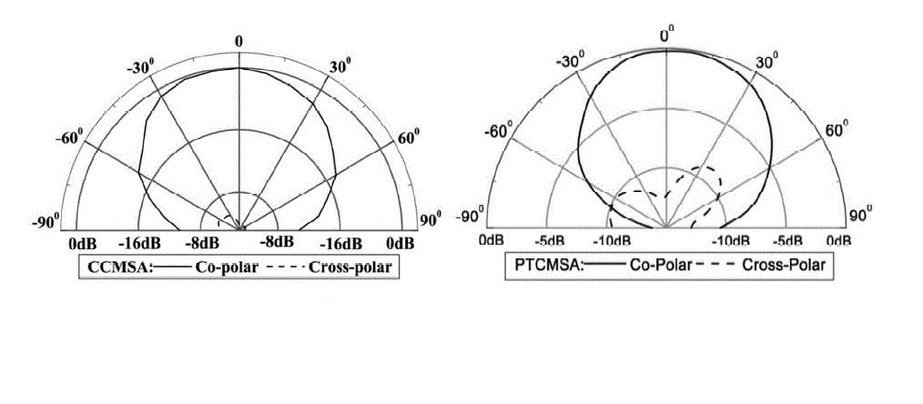
| The typical radiation patterns of co-polar and cross-polar are measured in the far field region at the resonating
frequencyfr (3GHz) of CCMSA and at fr1 (2.62 GHz) of PTCMSA are as shown in Fig. 5. From this figure, it can be
observed that, the patterns are broadside and linearly polarized. |
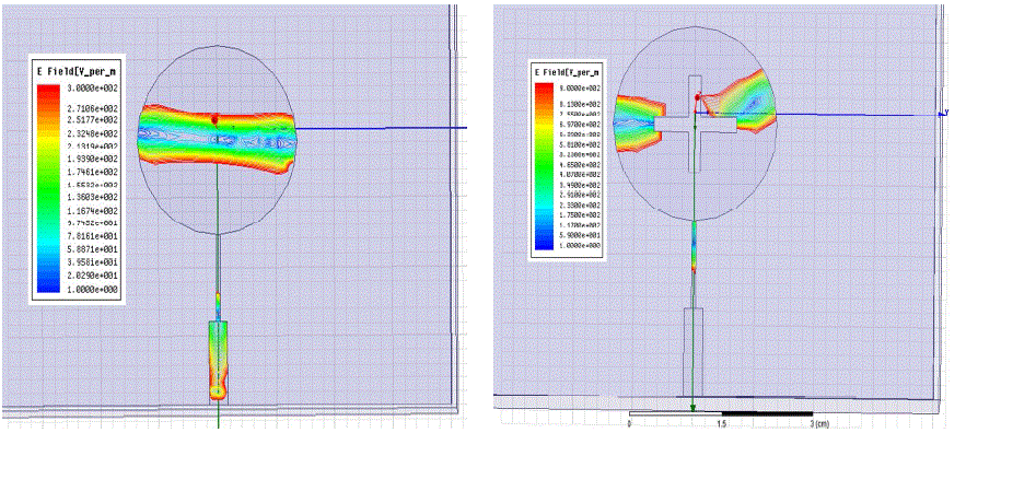
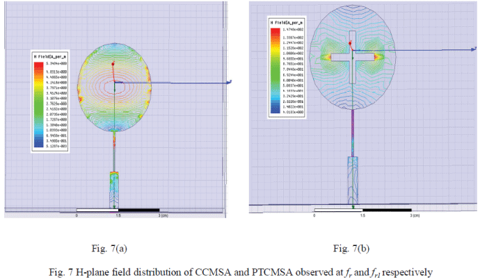
| Figure 6(a) and (b) shows the E- plane field distribution of CCMSA and PTCMSA observed atfr (3 GHz) and fr1 (2.62
GHz) respectively.Figure 7(a) and (b) shows the H-plane field distribution of CCMSA and PTCMSA observed at fr (3
GHz) and fr1 (2.62 GHz) respectively. From the figures 6 and 7 it is seen that, the field distribution is adequate on the
patch at the resonant frequencies indicates the effective radiation by the patch. |
CONCLUSION |
| In this paper, a new geometry (i.e. PTCMSA) has been proposed for penta band operation. This geometry has been
realized by placing the plus type slot at the centre of the CCMSA. The proposed antenna is operating between the
frequency range of 2.57 GHz to 11.09 GHz which is useful for WLAN and WiMAX applications. The PTCMSA gives
broadside radiation characteristics at each operating band. The PTCMSA is simple in its design and construction. This
antenna has been fabricated using low cost substrate material. These features make the antenna more attractive for
practical. |
ACKNOWLEDGMENT |
| The authors thank the authorities of Department of Science and Technology (DST), Govt. of India, New Delhi, for
sanctioning the Vector Network Analyser under the FIST project to the Department of Applied Electronics, Gulbarga
University, Gulbarga. |
Tables at a glance |
 |
| Table 1 |
|
| |
Figures at a glance |
 |
 |
 |
 |
| Figure 1 |
Figure 2 |
Figure 3 |
Figure 4 |
 |
 |
 |
| Figure 5 |
Figure 6 |
Figure 7 |
|
| |
References |
- Lal Chand Godara, Handbook of antennas in wireless communications, CRC Press, New York 2001.
- J.A. Ansari, A. Mishra, N. P. Yadhav, P. Singh and B. R. Vishvakarma, ?Analysis of L-shape slot loaded circular disk patch antenna for satellite and radio telecommunication?, Wireless Personal Communications, Springer US, Vol. 70, No. 2, pp. 927-943, 2013
- T. H. Kim and D. C. Park, ?CPW-fed compact monopole antenna for dual-band WLAN applications?, Electron. Lett.,vol.41, no.6, 2005
- Joong Han Yoon, young Chul Rhee and Yean Kil Jang, ?Compact monopole antenna design for WLAN/WiMAX triple-band operations?, Microwave Opt TechnolLett., Vol.54, No.8, 2012
- Z. X. Yuan, Y. Z. Yin, Y. Ding, B. Li and J. J. Xie, ?Multiband printed and double-sided dipole antenna for WLAN/WiMAX applications?, Microwave Opt TechnolLett., Vol.54, No.4, 2012
- R. K. Raja, M. Joseph, B. Paul and P. Mohanan, ?Compact planar multiband antenna for GPS, DCS, 2.4/5.8 GHz WLAN applications?, Electron. Lett.,Vol.41, No.6, 2005
- Yan Zhou and Claire Gu, ? A modified two-strip monopole antenna for WiFi and WiMAX applications?, Microwave Opt TechnolLett., Vol. 51, No.12, pp. 2884-2886, Dec. 2009.
- C. A. Balanis, Antenna theory analysis and design, John Willey & sons, New York, 1982.
|