Keywords
|
| Photovoltaic module, Incremental conductance algorithm, multi-rectifier, cuk converter, inverter power. |
INTRODUCTION
|
| Renewable energy has been one of the most attractive areas in research and development of power electronics in last decades. Different forms of renewable energy sources are available in nature such as, solar energy, wind energy, hydro energy etc…among this only hydro energy is made in use at present and the researches on other sources are going on. With the necessity of electricity, and the depletion of our present energy sources such as coal, charcoal, kerosene etc. lead to make use of solar and wind energy. Wind system can provide a better power output but its presence is unpredictable [1]. Solar energy is one of the good means to reduce these problems because they are available in plenty, free of cost and its eco-friendly nature .solar system does not causes any atmospheric pollution and never results in the emission of greenhouse gases, hence it attracts more attention to solve the energy crisis. Even if the solar system is economical, there is some loss factors such as solar irradiation, temperature, shadows, clouds etc. which affects the efficient working of the solar system. To make the system working properly and to extract maximum power from photovoltaic system, it is necessary to introduce an efficient MPPT algorithm[2]. Different MPPT algorithm methods like perturb and observe method, incremental conductance method, fuzzy logic method, neural network, etc. are presented. All these methods have their own advantages. Perturb and observe method is one the simplest and common method used in which it perturbs the duty cycle and controls the converter and there by obtain the next step through the p-v curve to track MPP. The main drawback of this method is oscillation at operating point. That is it cannot work efficiently at fast varying atmospheric conditions. This paper utilizes the most efficient and simplest method called incremental conductance method in which it can track the MPP exactly for a fast varying atmospheric condition. To track MPP an efficient rectifier is also required. Here the rectifier used is a fusion of two cuk converter. Cuk converter has more advantage compared to other forms of non-isolated dc-dc converters such as buck, boost and buck-boost converters, because it has less ripple current compared to others. This paper includes the circuit representation of proposed rectifier stage which can be used for multiple applications. Simulink model of PV system and incremental conductance method without PI controller with cuk-cuk rectifier stage and an inverter is also represented in this paper. |
PROPOSED TOPOLOGY
|
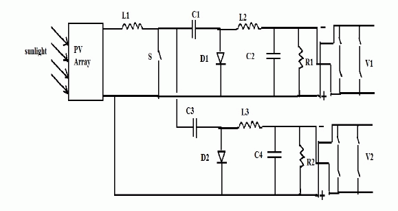
| Fig.1. shows the proposed topology. This consists of a Photovoltaic module, fusion of two cuk converters as rectifier stage, and an inverter at the output of each cuk converter. |
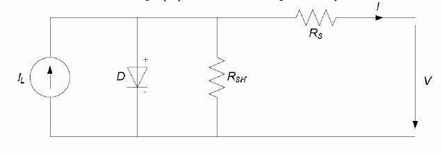
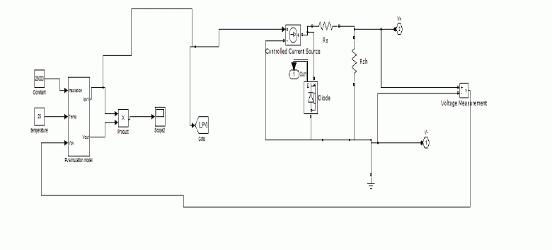
| Fig.2. shows the equivalent circuit of a typical solar cell. A solar cell is basically a p-n junction device which takes the advantage of photovoltaic effect, which is the ability to convert electromagnetic radiations into electric current. A number of such cells can be connected in either series or parallel depending on the voltage or current requirement. If such cells are connected in series or parallel, then it forms a PV array. Rs and Rsh are the series and shunt resistances of a solar cell. Rs is the resistance offered by the contacts and semiconductor material of the solar cell, hence it is of very small value, whereas Rsh is due to the impurities near the edges of the cell and it’s usually a larger value. |
| In the proposed circuit , the only input is the output obtained from a PV array. An efficient DC-Dc converter is necessary to extract maximum power from a PV system. The proposed system contains a rectifier stage and it is the fusion of two cuk converter. The fusion of these converters is achieved by sharing the input inductor and switch of first converter by the other converter [1], [5]. This configuration allows the converters to operate normally from the same input source and allow it use for multiple applications. There are different types of non-isolated dc-dc converters are available, among all these cuk converter is more advantages when compared to other converters because in cuk converter the source and load side are separated by means of a capacitor C1,through which the energy is transferred from the source side to load side, thereby current ripples are less in both source and load sides when compared to other converters. The other advantage of cuk converter is input and output current is continuous and hence switching loss is very less and has better efficiency. |
| When the switch is in off condition then, the capacitor C1 is charged from the input supply and the energy stored in the inductor L2 is transferred to load. |
| When the switch is on ,then the voltage across the inductor L1 and L2 are shown in equation (1) and (2) |
 |
| When the switch is off, then the voltage across the inductor L1 and L2 are shown in equation (3) and (4) |
 |
| When the converter operates under steady state condition, then the average value of inductor voltage over a time period is equal to zero.hence the relation between input and output voltage as well as current is given in the equation (5) |
 |
| Here D is the duty cycle, Vd and Vo are the input and output voltages. The output obtained from the cuk converter is of opposite polarity with respect to its input and is of a dc voltage. Hence an inverter is connected at its output to convert it into ac for ac application. |
PV MODULE AND MPPT CONTROL OF PROPOSED CIRCUIT
|
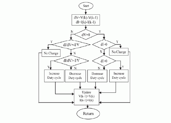
| Solar energy is one of the good means to generate required electricity, because it is eco-friendly and it is available in plenty and throughout the day. But there is some loss factors such as temperature, solar irradiation, etc. which affects the efficient working of the PV module. Solar irradiation will vary with unpredictable shadows, or due to sun intensities. The photon generated current is highly depends on the solar irradiation level. Hence it is necessary to introduce an effective method to track the maximum power output of a PV system. MPPT or maximum power point tracking is an effective method to track the maximum power point of a PV system. There are different MPPT methods such as Perturb and observe method, incremental conductance, dp/dv method, fuzzy system, neural network etc...perturb and obseve method is one of the simplest method and it involves the perturbation of the duty cycle of the converter and and controls it and it gets the next step to find the MPP. even if it is a simple method , there is some oscillations occurs at the MPP[1]-[4]. That is it cannot work properly to the fast changing atmospheric condition. The incremental conductance method [2] is one of the simplest and the efficient method which can track the MPP exactly. In this method the error is generated by adding the instantaneous conductance and incremental conductance. This method is an advanced form of dp/dv method .In incremental conductance method the slope of P-V curve is zero at maximum power point and it is increasing on left of MPP and decreasing on its right half [3]. The equation which represents the above are |
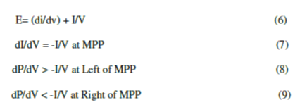 |
| Incremental conductance method without PI controller is used here. The flow chart of typical incremental conductance method [3] is given below. |
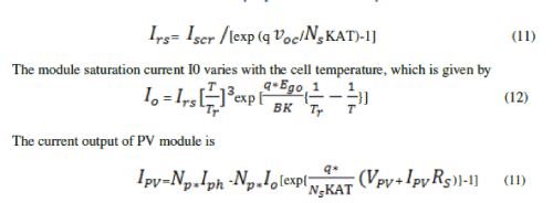
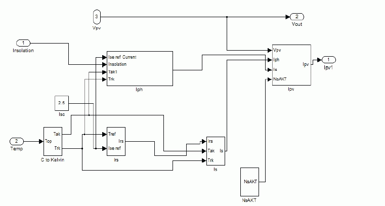
| The PV module [6] is formed using the equation given below. |
| Module photo current |
 (10) (10) |
| Module reverse saturation current |
 |
SIMULATION RESULTS
|
| To examine the performance of the proposed multi output converter shown in fig 1, it’s simulated. MAT Lab software is used for simulation purpose. Here switch is composed of a MOSFET with an antiparallel diode. The mathematical model of both PV module [6] and incremental conductance [7] was developed using equations and its shown in the figure 5 and 6. |
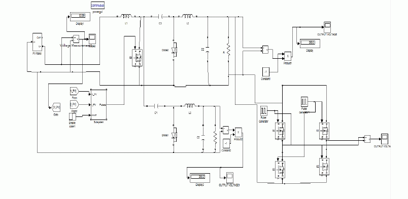
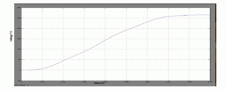
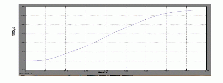
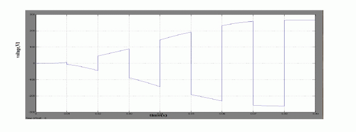
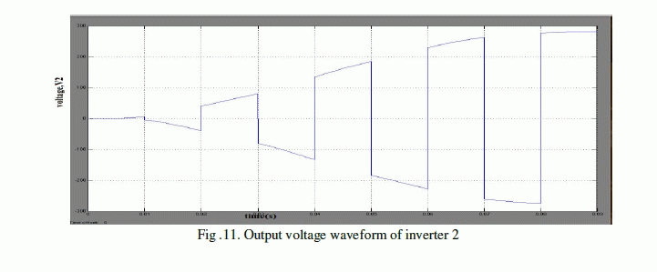
| Figure 7 shows the Simulink model of proposed circuit and figure 8, 9, 10 and 11 shows the output voltage obtained for cuk converter1, converter2 and the inverters. Both the converters are fed from the same solar system. Here the output of each converter is greater than the input voltage applied. The output voltage of solar system is 53.7V and it’s the input applied to both converters. The output voltage ,V1 and V2 are 264.5V and 280.3V respectively. The initial duty ratio chosen for above simulation is 0.7 [7]-[8]. We can choose the value of D, the duty cycle either greater than or less than 0.5, depending upon the voltage requirement of each application. Different values are chosen for the inductors, capacitors, etc of each converter. |
CONCLUSION
|
| In this paper a new multi output rectifier stage is proposed. The proposed topology combines two cuk converter by sharing the input inductor and switch. There by the complexity of circuit is minimized and increases the reliability. The proposed circuit can be used for low to medium voltage application. Since it uses the fusion of two cuk converter, depending upon the voltage required for a particular application, the voltage can be either step up or step down by adjusting the duty cycle. The proposed circuit has less switching loss, continuous input and output current and better efficiency. The circuit can be used to drive different equipment that are operated with different voltages. |
Figures at a glance
|
 |
 |
 |
 |
| Figure 1 |
Figure 2 |
Figure 3 |
Figure 4 |
 |
 |
 |
 |
| Figure 5 |
Figure 6 |
Figure 7 |
Figure 8 |
 |
 |
 |
 |
| Figure 9 |
Figure 10 |
Figure 11 |
Figure 12 |
|
| |
References
|
- Joanne Hui, AlirezaBakhshai, and Praveen K. Jain, “ a hybrid wind solar energy system: A new rectifier stage topology”, 2010 IEEE
- M.Lokanadham, K.VijayaBhaskar, “Incremental Conductance Based Maximum Power Point Tracking (MPPT) for Photovoltaic System,”International Journal of Engineering Research and Applications (IJERA) ISSN: 2248-9622 Vol. 2, Issue 2,Mar-Apr 2012, pp.1420-1424
- Harsha P.P., DhanyaP.M ,Karthika K, “Simulation & Proposed Hardware Implementation of MPP controller for a Solar PV system,” ISSN(Print) : 2278-8948, Volume-2, Issue-3, 2013
- KinalKachhiya, MakarandLokhande, Mukesh Patel “MATLAB/Simulink Model of Solar PV Module and MPPT Algorithm,” NationalConference on Recent Trends in Engineering & Technology, 13-14 May 2011.
- Amarnath Kurella1, R Suresh , “Simulation Of Incremental Conductance Mppt With Direct Control Method Using Cuk Converter , IJRET:International Journal of Research in Engineering and Technology eISSN: 2319-1163 | pISSN: 2321-7308 , Volume: 02 Issue: 09 | Sep-2013
- N. Pandiarajan, RanganathMuthu “Mathematical ModelingofPhotovoltaic Module with Simulink ,” International Conference on ElectricalEnergy Systems (ICEES 2011), 3-5 Jan 2011
- Syam M S, T.Sreejith Kailas “Grid Connected PV System using Cuk Converter,” International Conference on Microelectronics,Communication and Renewable Energy (ICMiCR-2013)
- Ki-Bum Park, , Gun-Woo Moon, and Myung-JoongYoun” Nonisolated High Step-up Boost Converter Integrated With Sepic Converter” IEEE Transactions On Power Electronics, Vol. 25, No. 9, September 2010
|