Keywords
|
| Active Power filter, Passive power filter, Harmonics compensation, Power factor correction, Power quality. |
INTRODUCTION
|
| In recent years both power engineers and consumers have been giving focus on the “electrical power quality” i.e. degradation of voltage and current due to harmonics, low power factor etc. A power quality problem exists if any voltage, current or frequency deviation results in a failure or in a bad operation of customer’s equipment. So, for the better performance of the system it should be free from harmonics. For that purpose filters are used. There are so many types of filters such as active filter, passive filter, recently power quality has become one of the most important issues in modern power industry. The origin of events which affect quality of power is mainly electromagnetic transients, harmonic distortion in addition to voltage sag, swell, flicker, and other power quality disturbances that proliferate in modern electric power grids. Power quality means the physical characteristics of the electrical supply provided under normal operating conditions that do not disturb the customer’s processes [1]. |
POWER QUALITY
|
| “Power quality” is defined as âÃâ¬Ãâ¢the concept of powering and grounding electronic equipment in a manner that is suitable to the operation of the equipment in a manner that is suitable to the operation of that equipment and compatible with the premise wiring system and other connected equipment. Power quality has become a strategic issue for the following reasons: |
| 1. The economic necessity for businesses to increase their competitiveness. |
| 2. The widespread use of equipment which is sensitive to voltage disturbances and /or generates disturbances itself. |
| 3. The deregulation of the electricity market. In this context, it is essential for the utility and the customers to prevent and detect power quality problems and to have solutions available to fix them. |
| 4. The power quality correction and harmonic filtering system give solution to solve the problems of harmonic disturbances and voltage fluctuations [2]. |
| Most of the more important international standards define power quality as the physical characteristics of the electrical supply provided under normal operating conditions that do not disrupt or disturb the customer’s processes. Therefore, a power quality problem exists if any voltage, current or frequency deviation results in a failure or in a bad operation of customer’s equipment. However, it is important to notice that the quality of power supply implies basically voltage quality and supply reliability. Voltage quality problems relate to any failure of equipment due to deviations of the line voltage from its nominal characteristics, and the supply reliability is characterized by its adequacy and availability. Power quality problems are common in most of commercial, industrial and utility networks. Natural phenomena, such as lightning are the most frequent cause of power quality problems. Switching phenomena resulting in oscillatory transients in the electrical supply, for example when capacitors are switched, also contribute substantially to power quality disturbances. Also, the connection of high power non-linear loads contributes to the generation of current and voltage harmonic components. Between the different voltage disturbances that can be produced, the most significant and critical power quality problems are voltage sags due to the high economical losses that can be generated. Shortterm voltage drops (sags) can trip electrical drives or more sensitive equipment, leading to costly interruptions of production. For all these reasons, from the consumer point of view, power quality issues will become an increasingly important factor to consider in order to satisfy good productivity. On the other hand, for the electrical supply industry, the quality of power delivered will be one of the distinguishing factors for ensuring customer loyalty in this very competitive and deregulated market. To address the needs of energy consumers trying to improve productivity through the reduction of power quality related process stoppages and energy suppliers trying to maximize operating profits while keeping customers satisfied with supply quality, innovative technology provides the key to cost-effective power quality enhancements solutions. However, with the various power quality solutions available, the obvious question for a consumer or utility facing a particular power quality problem is which equipment provides the better solution [3]. |
POWER QUALITY IMPROVEMENT WITH THE HELP OF DIFFERENT TYPES OF FILTERS
|
| Basically two types of filters are used in methods of Power Quality improvement such as Active Power filter and Passive Power filters. Detailed Explanation and solution of power quality with the use of these filters is described below:- |
ACTIVE POWER FILTER
|
| An active filter is a type of analog electronic filter that uses active components such as an amplifier. Amplifiers included in a filter design can be used to improve the performance and predictability of a filter, while avoiding the need for inductors (which are typically expensive compared to other components). An amplifier prevents the load impedance of the following stage from affecting the characteristics of the filter. An active filter can have complex poles and zeros without using a bulky or expensive inductor. The shape of the response, the Q (quality factor), and the tuned frequency can often be set with inexpensive variable resistors. In some active filter circuits, one parameter can be adjusted without affecting the others. Using active elements has some limitations. Basic filter design equations neglect the finite bandwidth of amplifiers. Available active devices have limited bandwidth, so they are often impractical at high frequencies. Amplifiers consume power and inject noise into a system. Certain circuit topologies may be impractical if no DC path is provided for bias current to the amplifier elements. Power handling capability is limited by the amplifier stages. Active filters are special equipments that use power electronic converters to compensate for current and/or voltage harmonics originated by non-linear loads, or to avoid that harmonic voltages might be applied to sensitive loads. There are basically two types of active filters: the shunt type and the series type [4]. |
SHUNT ACTIVE POWER FILTER
|
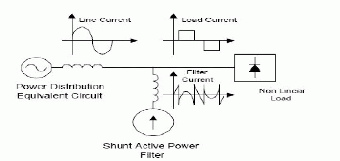
| Shunt active power filter compensate current harmonics by injecting equal-but-opposite harmonic compensating current. In this case the shunt active power filter operates as a current source injecting the harmonic components generated by the load but phase shifted by 180âÃÂð. This principle is applicable to any type of load considered a harmonic source. Moreover, with an appropriate control scheme, the active power filter can also compensate the load power factor. In this way, the power distribution system sees the non linear load and the active power filter as an ideal resistor [5]. The current compensation characteristic of the shunt active power filter is shown in Figure. |
CONTROL SCHEME
|
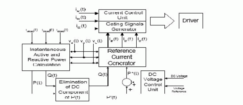
| The block diagram of a shunt active power filter control scheme is shown in Figure and consists of a current reference generator, a dc voltage control and the inverter gating signals generator. The current reference circuit generates the reference currents required to compensate the load current harmonics and reactive power, and also try to maintain constant the dc voltage across the two electrolytic capacitors. There are many possibilities to develop this type of control. Also, the compensation effectiveness of an active power filter depends on its ability to follow with a minimum error and time delay the reference signal calculated to compensated the distorted load current. Finally, the dc voltage control unit must keep the total dc bus voltage constant and equals to a given reference value. The dc voltage control is achieved by adjusting the small amount of real power absorbed by the inverter. This small amount of real power is adjusted by changing the amplitude of the fundamental component of the reference current figure. |
SERIES ACTIVE POWER FILTER
|
| It is well known that series active power filters compensate current system distortion caused by non-linear loads by imposing a high impedance path to the current harmonics which forces the high frequency currents to flow through the LC passive filter connected in parallel to the load. The high impedance imposed by the series active power filter is created by generating a voltage of the same frequency that the current harmonic component that needs to be eliminated. Voltage unbalance is corrected by compensating the fundamental frequency negative and zero sequence voltage components of the system. |
CONTROL SCHEME
|
| The block diagram of the proposed control scheme is shown in Figure 6. Current and voltage reference waveforms are obtained by using the Instantaneous Reactive Power Theory. Voltage unbalance is compensated by calculating the negative and zero sequence fundamental components of the system voltages. These voltage components are added to the source voltages through the series transformers compensating the voltage unbalance at the load terminals. In order to reduce the amplitude of the current flowing through the neutral conductor, the zero sequence components of the line currents are calculated. In this way, it is not necessary to sense the current flowing through the neutral conductor. Where Pref and qref are the instantaneous active and reactive power associated with harmonics current components. |
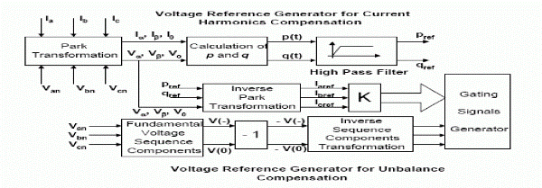 |
| The block diagram of the proposed series active power filter control scheme [9] |
PASSIVE POWER FILTERS
|
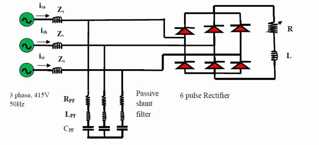
| The passive filters are used to mitigate power quality problems in six-pulse ac-dc converter with R-L load. Moreover, apart from mitigating the current harmonics, the passive filters also provide Reactive power compensation, thereby, further improving the system performance. For current Source type of harmonic producing loads, generally, passive shunt filters are recommended. These filter apart from mitigating the current harmonics, also provide limited reactive power Compensation and dc bus voltage regulation.[10] There are basically two types of passive filters, the shunt type and the series type. |
SHUNT PASSIVE POWER FILTER
|
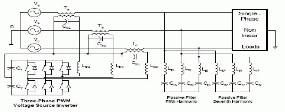
| Figure shows the schematic diagram of a passive shunt filter connected at input ac mains of six pulse ac-dc converter with R-L load. This is the most commonly used configuration of passive filters. In this configuration different branches of passive tuned filters (low pass and high pass) tuned for the more dominant harmonics are connected in parallel with the diode rectifier with RL load. It consists of a set of low pass tuned shunt filters tuned at 5th and 7th harmonic frequencies and high pass tuned for 11th harmonic frequency. This passive filter scheme helps in sinking the more dominant 5th and 7th and other higher order harmonics and thus prevents them from flowing into ac mains. The diversion of harmonic current in the passive filter is primarily governed by the source impedance available in the system. The higher value of source impedance offers better performance of the passive filter |
SERIES PASSIVE POWER FILTER
|
| For voltage source type of harmonic loads (such as diode rectifier with R-L load filter), passive series filter is considered as a potential remedy for harmonic mitigation. Here, the different tuned branches of passive filters are connected in series with the supply and the diode rectifier. Shows the schematic diagram of a passive series filter connected at input ac mains. It consists of a set of low block tuned shunt filter tuned at 5th and 7th harmonic frequencies and high block tuned filter for 11th harmonic frequency. These passive filters blocks most dominant 5th, 7th and other higher order harmonics and thus prevents them from flowing into ac mains. Here, the performance of the series filter is not much dependent on the source impedance. However, it results in reduction in dc bus voltage due to voltage drop across filter components. |
 |
| Schematic diagram of a ac-dc converter with R-L load and passive series filter at input. [11] |
CONCLUSION
|
| This paper deals with problems related with harmonics in power system networks. Several international standards Issued to control power quality problems are briefly described and some important tools to analyze electrical Circuits with non-sinusoidal waveforms are introduced and evaluated. Among other application, these tools are useful in the implementation of control algorithms for filters. |
Figures at a glance
|
 |
 |
 |
 |
| Figure 1 |
Figure 2 |
Figure 3 |
Figure 4 |
|
| |
References
|
- MetkariArchanaSubhash, Prof.S.H.Pawar, “Improvement of power quality by using active filter based on vectorial power theory control strategy on the MATLABSimulinkplatform”, IOSR Journal of Electronics and Communication Engineering (IOSR-JECE) ISSN: 2278-2834, ISBN: 2278-8735, PP : 37-40.
- G.Ravindra, P.Ramesh, Dr.T.Devaraju “Enhancement of Power Quality Using Active Power”, International Journal of Scientific and Research Publications, Volume 2,Issue 5, May 2012 1 ISSN 2250-3153.
- wikipedia.org/wiki/Active filter.
- SahebHussain MD, K.Satyanarayana, B.K.V.Prasad“ POWER QUALITY IMPROVEMENT BY USING ACTIVE POWER FILTERS” IJESAT. INTERNATIONAL JOURNAL OF ENGINEERING SCIENCE & ADVANCED TECHNOLOGY Volume - 1, Issue - 1, 1 – 7.
- João L. Afonso, Member IEEE, H. J. Ribeiro da Silva and Júlio. S. Martins, Member IEEE “Active Filters for Power Quality Improvement” 2001 IEEE Porto PowerTech, 10-13 Set. 2001, Porto, Portugal, ISBN: 0 7803 7139 9
- NazmusSahadat, Shakhawat Hossain, Arifur Rahman, Sharif Taufique Atique, Md. Touhiduzzaman “ Power Quality Improvement of Large Power System Using aConventional Method” Engineering, 2011, 3, 823-828 doi:10.4236/eng.2011.38100 Published Online August 2011 (http://www.SciRP.org/journal/eng).
- B.VenkataRamana,S.DayasagarChowdary, G.VenkataRatnam “Analysis of Active and Passive Power Filters For Power Quality Improvement underDifferent LoadConditions” International Journal of Advanced Research in Electrical, Electronics and Instrumentation Engineering(An ISO 3297: 2007 Certified Organization)Vol. 3,Issue 8, August 2014.
- RACHID DEHINI SLIMANE SEFIANE “POWER QUALITY AND COST IMPROVEMENT BY PASSIVEPOWER FILTERS SYNTHESIS USING ANT COLONY ALGORITHM. RACHID DEHINI” Journal of Theoretical and Applied Information Technology.
- C.NaliniKiran, SubhransuSekhar Dash, S.PremaLatha “A Few Aspects of Power Quality Improvement Using Shunt Active Power Filter” International Journal ofScientific & Engineering Research Volume 2, Issue 5, May-2011
- H. AKAGI “Modern active filters and traditional passive filters” BULLETIN OF THE POLISH ACADEMY OF SCIENCESTECHNICAL SCIENCES Vol. 54, No.3, 2006
- K. Swarna Pujitha, EPS, D. Gowtami “Enhancement Of Power Quality By Using Modified Power Filter And Compensator In Grid Network” INTERNATIONAL JOURNAL OF SCIENTIFIC & TECHNOLOGY RESEARCH VOLUME 3, ISSUE 8, AUGUST 2014.
|