ISSN ONLINE(2319-8753)PRINT(2347-6710)
ISSN ONLINE(2319-8753)PRINT(2347-6710)
Niruban Projoth T 1, Balamurali M 2, Vignesh R 3
|
| Related article at Pubmed, Scholar Google |
Visit for more related articles at International Journal of Innovative Research in Science, Engineering and Technology
Resource allocation is a major interest in the field of Manufacturing Industry because of their practical significance. For manufacturing processes, cost of the raw material usually forms a significant portion of the input costs, it is therefore desirable that this resource be used efficiently. The proposed work studies the allocation of rectangular and irregular polygon shaped parts within available sheet material to achieve better utilization factor and reduction in cost. Preliminary studies were done to decide the principal components of interest in the optimization process. A comparative study is also made on the traditional bottom left positioning and random positioning based non guillotine approach allocation to substantiate the factors affecting the nesting process optimization.
Keywords |
| Bottom left approach, Nesting Process, Optimization, Random allocation. |
INTRODUCTION |
| In today’s competitive manufacturing environment, manufacturing industries are working hard to improve productivity, as well as reduce cost and leadtime. An important issue faced by the sheet metal cutting industries and other manufacturing industries works on how to find the optimum layout of 2D parts with different shape and size within the available sheet, such that the material utilization can be maximized and the resulting material wastage can be minimized. In some manufacturing industries, operators decide the layout from their own experience, but this is not an efficient method because the results do not efficiently utilize the raw material. |
| To find the most efficient layout for the parts in a given sheet with minimal wastage, nesting process is used such that to attain optimality. Nesting is a problem in which many researchers working on the same problem by many algorithms to nest complex and multiplex parts which will maximize the utilization of the resources. Cutting that has to be done after allocation of parts in a sheet undergoes two classification (i) Non-guillotine cutting framework, in which after each cut the detached parts are not considered as separate entities and a common cut can be made to both the parts. Also, the cuts made need not necessarily be from edge to edge. (ii) Guillotine cutting framework, in which once a cut is made, the detached parts are treated as separate entities such that every single cut has to be from edge to edge for any particular rectangular part. This article deals with Non-guillotine cutting framework since it is considered to be an efficient way of cutting compared to guillotine cutting framework. Also, it brings a comparative study on the traditional bottom left positioning and random positioning based non guillotine approach allocation to substantiate the factors affecting the nesting process optimization. |
| S.Q. Xie et al [1] reports an intelligent computer-aided nesting ( CAN ) system for optimal nesting of two – dimensional parts, especially parts with complicated shapes, with the objective of effectively improving the utilization ratio of sheet materials. Mohamed A. Shalaby et al [2] developed and tested a sequence-based approach involves optimization phase and placement phase. The optimization phase searches for the packing sequence that would lead to an optimal solution when translated to an actual pattern through the placement phase. S.K. Cheng et al [3] proposed the typical nesting technique that is widely used is the geometrical tilting of single pattern or selected cluster step by step from the original position to an orientation of certain degrees. This is a blind search of best stock layout and geometrically it becomes inefficient when several pattern entities are involved. Indrajit Mukherjee et al [4] classified the application potential of several modelling and optimization techniques in metal cutting processes under several criteria and a generic framework for parameter optimization in metal cutting processes is suggested for the benefits of selection of an appropriate approach. |
| Weng and Kuo et al [5] presented an irregular stock cutting system (NEST) developed on AutoCAD software platform by VBA programming language. Bennell and Oliveria et al [6] provided the detailed explanations of the most popular techniques for handling the geometry when solving nesting problems and provide guidance on their implementation, strengths and weaknesses. The techniques are raster method, direct trigonometry, No-fit polygon and phi functions. Lam et al [7] presented an automatic nesting system for relatively more complex parts is devised and implemented on the computer software tool solid works, and visual C++ is used to create the solid works application programming interface for algorithm demonstration. Liu in [8] introduced a system of optimizing nesting with an analogical learning mechanism The analogical learning mechanism is applied at two points: the combination of irregular parts in the pre-treatment and the nesting process of blocks |
II. PROBLEM FORMULATION |
| Assume a sheet metal which is to be used for efficient allocation of the irregular shapes in random method with infinity length. Irregular parts will be selected which are to be placed on sheet metal and the algorithm should ensure on the maximum material utilization for generalised nesting process. Finally, simulate the developed algorithms by using MATLAB programming. |
| The main aim of the article deals with the process of analysing the cases on different approaches and to find the factors influencing the nesting process optimization and thus it will be easy to compare by finding the performance of different allocation process and to compare each. So the different allocation processes are taken into consideration are: |
| 1) Random Allocation |
| 2) Bottom Left/Right Approach |
| A. Random allocation: |
| Random Allocation denotes the parts that have a chance to get allocated in the sheet in a random manner. For the better understanding of the problem in random allocation, it will be easy to specify the parts and its allocation in accordance to its sequence. The algorithm for Random Allocation is given below: |
| Step 1: Read the number of Parts and the dimensions of each part. |
| Step 2: Initialize the sheet metal space and determine the order in which the parts are to be taken into consideration for placing. |
| Step 3: Read the Part details of the 1st part under consideration. |
| Step 4: Determine a random point in the sheet metal space and check for the following constraints. |
| (1) With the random point as the origin check whether the point is within the range to place the part so that the length of the part will not cross the boundary of the sheet metal. |
| (2) With the same random point as the origin check whether the point is within the range to place the part so that the breadth of the part will not cross the boundary of the sheet metal. |
| (3) If both the above conditions satisfy then place the part at the chosen random point and check whether there is any overlap. |
| Step 5: If any of the above three conditions fail to satisfy, then discard the chosen random point and Increase the flag variable by 1 after choosing another random point and proceed to step 4. |
| Step 6: If the flag variable reaches a value of 100, then go to Step 9 |
| Step 7: Check whether all the parts have been placed or else read the details of the next part and proceed to step 4. |
| Step 8: If all parts have been placed, display the output. |
| Step 9: If flag variable reaches 100 then display that the problem fails to converge to place the part. |
| Fig. 1 shows the part that has been taken as an example to check the allocation in a random manner. The MATLAB is programmed in such a way to get the output in random manner. |
 |
| Different allocation of parts at each run is checked by different solutions that has been got is shown in Figure 2. |
 |
B. Bottom left approach: |
| In this paper, we use a approach of Bottom Left (BL) algorithm. In the BL algorithm, the piece is firstly put at the left upper corner of the stock plate and then it is moved further. When the piece moves towards the sheet bottom, if there is any overlapping exists, it will move slightly towards the right and again tries to reach the bottom or the previous part that has been placed. Such that the program is repeated until all the parts get placed in the sheet. |
| Step 1: Sort the pieces in ascending order of base length. |
| Step 2: Place the first piece on the stock plate according to the coordinates of the left bottom comer. |
| Step 3: Call the procedure of “moving one piece” to move the piece. |
| Step 4: If all pieces have been treated, go to Step 5, otherwise place next piece on the stock according to the coordinates of the left bottom, go to Step 3. |
| Step 5: Place the pieces that are unplaced, on the right upper comer of the stock plate. |
| Step 6: Call the procedure of “moving one piece” to move the piece. |
| Step7: If all pieces have been placed, terminate the layout process, otherwise place next piece on the right comer of the stock plate, go to Step 6. |
| Thus the results found i.e., each randomly allocated sequence will be having different performance efficiency and the each will be taken into account while comparing the performance measure of other allocations using different algorithms as well. In the same way, the article have a keen outlook on the comparison on the results with the bottom left approach and top right corner approach. |
C.Utility factor: |
| To compare the effectiveness of various methods and the efficiency of their allocation, the utility Factor can be used as a performance measure. Utility Factor can be defined as the ratio of Sum of Effective Area of All the parts to the Total Rectangular Allocated Area allocated by the method. |
 |
| The following cases deals with the finding the fitness functions that affect the solution by certainly taking the sequence order as a factor and in which the variation in the area shows the effect of allocation of parts in the sheet, certain cases are considered that are as follows: |
III.CASES |
A. Case 1: Rectangular Parts: |
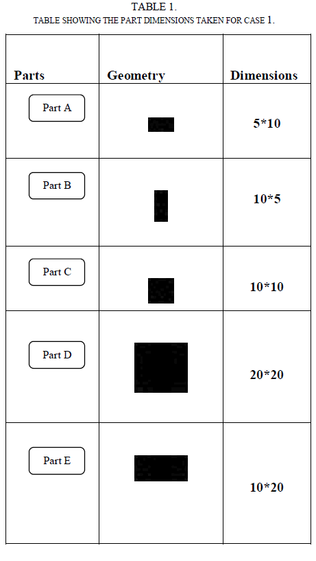 |
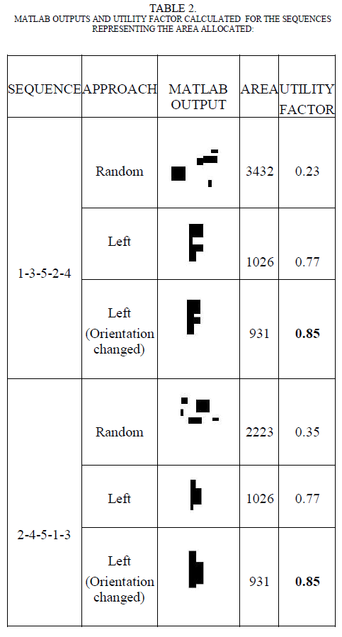
| In this case, rectangular pieces of different dimensions are taken to check the variance in the area allocated for the parts in the sheet. In the total possible solution, there can be number of variation in the area allocated in which only some sequences can be treated to be an optimized one. For that reason, the article discuss with two different sequences as in Table 2. |
 |
| Total Possible Solutions = 5! = 5*4*3*2*1 = 120. |
| The two sequences 1-3-5-2-4 and 2-4-5-1-3 are taken as the examples to explain the variation in the area and the utility factor in table 2. The random approach allocates the parts in a random manner such that they get different allocation on each run. But during the bottom left approach, there is a variation in the area such that it will be the same for all the sequences or the parts in which it is taken. In this case, the sequence has not affected the utility factor. But when the orientation of a part is changed like in this case, the orientation of Part B is changed to take a 90o rotation, which affects the area allocated and the utility factor. |
| From case 1, it has been inferred that the orientation change affects the utility factor which serves to be a main factor in optimizing the resource allocation. |
B. Case 2: Irregular parts: |
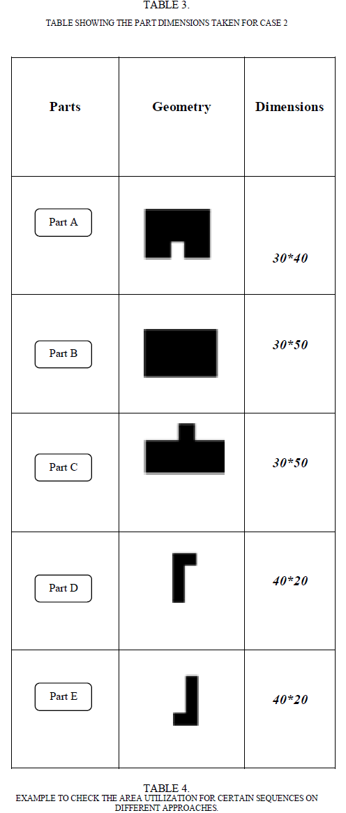
| In this case, Irregular polygon parts are taken into consideration such that to see how the nesting takes place with respect to the sequence and how it affects the optimization on the resource allocation. The Table. 3 shows the parts that has been chosen for the case 2, in which the parts are taken in which there is only one possible best solution occurs out of the total possible solutions. |
 |
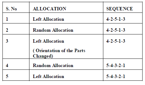 |
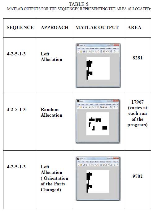
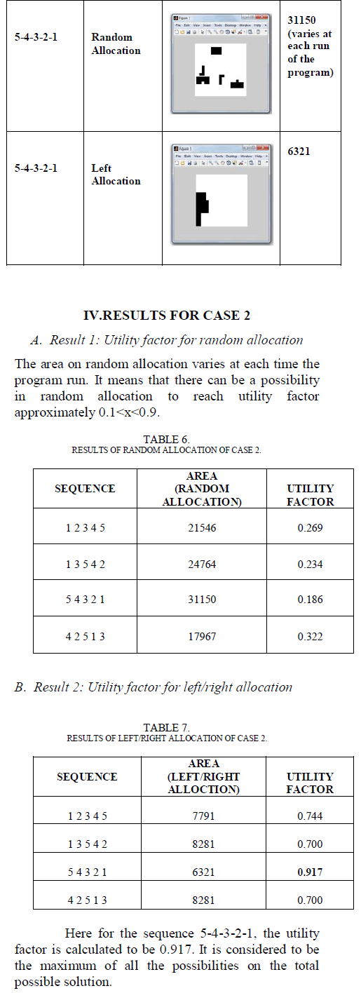
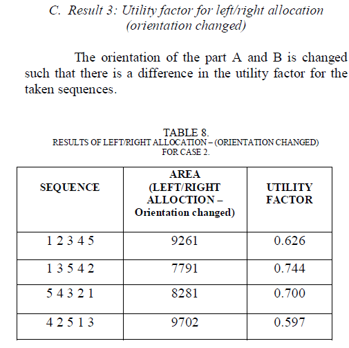
| Here, the different cases are taken in such a way to find the difference between the area allocated in each cases where the allocation and sequence gets change as shown in the table 5.1. The sequence 4-2-5-1-3 is taken as a case for each type of allocation and the regarding area allocated for the respective type of allocation is shown below. Also the sequence 4-2-5-1-3 in which the orientation is changed for any two parts is taken in order to specify whether the orientation change affects the area allotted. The sequence 5-4-3-2-1 is taken such that it could give a optimal solution of allocation in its left/right allocation, where the area allocated will be less than all the possible sequences. The random allocation of this sequence and the left allocation is simulated using the MATLAB, and the area allocated is found. |
 |
 |
 |
V. CONCLUSION AND DISCUSSIONS |
| Thus from the results of case 1 and case 2, it is inferred that for the same sequence, the utility factor varies in accordance to the method of selection. The sequence order and the orientation of the parts changes the total area allocated to different parts of different geometric dimensions. Certain Factors affecting the nesting process optimization was found as follows: |
A. Geometry of the Parts: |
| The dimensions of the parts play a major role in the allocation process. The geometry of the part is considered to be one of the factors affecting the nesting process optimization. |
B. Changing the Parts Order: |
| The part order or the sequence of the different parts acts to be a main factor that affects the fitness function. From the discussed cases, the change in the part order of allocation in the sheet metal affected the utility factor of the allocation. Thus it plays a key role in the nesting process optimization. |
C. Changing the Orientation of the Parts: |
| The orientation of the parts i.e., vertical, horizontal or rotated at an angle will disturb the solution such that it deserves to be a fitness factor affecting the solution. |
References |
|