Keywords
|
| WLAN, UMTS, OPNET, GRE, MIPV4, SGSN, GGSN |
INTRODUCTION
|
| Over recent years, telecommunications has been a fast-growing industry. This growth can be seen in the increasing revenues of major telecommunications carriers and the continued entry into the marketplace of new competitive carriers. No segment of the industry, however, has seen growth to match that experienced in mobile communications. From relatively humble beginnings, the last 15 years have seen an explosion in the number of mobile communications subscribers and it appears that growth is likely to continue well into the future. |
| The growth in the number of mobile subscribers is expected to continue for some years, with the number of mobile subscribers surpassing the number of fixed network subscribers at some point in the near future. Although it may appear that such predictions are optimistic, it is worth pointing out that in the past, most predictions for the penetration of mobile communications have been far lower than what actually occurred. In fact, in several countries, the number of mobile subscribers already exceeds the number of fixed subscribers, which suggests that predictions of strong growth are well founded. |
| The objective of the 3G was to develop a new protocol and new technologies to further enhance the mobile experience. In contrast, the future 4G framework is expected to accomplish new levels of user experience and multiservice capacity by also integrating all the mobile technologies that exist (e.g. GSM, GPRS, 3G, Wi-Fi, and Bluetooth). There are different approaches, with different visions of the future platform currently under investigation. The main objectives of 4G networks can be stated in the following properties: |
| • Ubiquity |
| • Multi-service platform |
| • Low bit cost |
A SHORT DESCRIPTION OF MIPV4
|
| Mobile IP version 4 defined in RFC 3344 or MIPv4 is a routing protocol standardized by the IETF (Internet engineering task force) to offer Internet mobility to the mobile hosts. It is applicable on top of current IPv4 wired network without any need of modification in the existing fixed hosts and routers. A mobile host needs to be allowed to change its access location under mobile condition while retaining its IP address associated with the fixed network where as a higher layer connection does not allow changes of either the source or destination IP address. Other important issues such as security, Internet mobility management and QOS are also of great concern in designing the protocol. |
OVER VIEW OF GNERIC ROUTING ENCAPSULATION
|
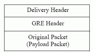
| GRE in its simplest form provides a way to encapsulate any network layer protocol over any other network layer protocol. For the SROS (secure router operating system) implementation, GRE is used to transport IP packets with private IP addresses over the public internet to a remote private IP network. GRE allows routers to act as if they have a virtual point-to-point connection to each other. GRE tunnels allow routing protocols (like RIP and OSPF) to be forwarded to another router across the Internet. In addition, GRE tunnels can encapsulate multicast data streams for transmission over the Internet. Suppose a system has a packet that needs to be encapsulated and routed. This is called as payload packet. The payload is first encapsulated in a GRE packet, which includes a route of its own. The resulting GRE packet can then be encapsulated in some other protocol and forwarded. This outer protocol is called delivery protocol [1]. GRE packets which are encapsulated within IP will use IP protocol type 47[16]. The entire encapsulated packet looks like following. |
| addresses of UMTS are assigned from a pool of GGR address. All the IP packets destined for the UMTS users are routed to the GGR. GGR checks the MIP binding for each received packet. If no MIP binding exists, the GGR assumes that the packet is destined for user which is in the UMTS network. So, it forwards the packet to GGSN. |
PROPOSED INTERCONNECTION ARCHITECTURE
|
| Among many Integration schemes proposed by several authors in different literatures we have preferred the loosely coupled architecture due to some architectural advantages over other architectures stated above. |
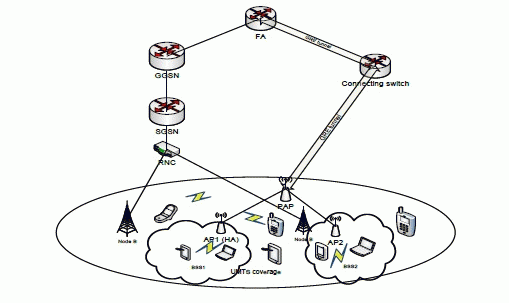
| In the above architecture we have integrated an UMTS network with an 802.11 a WLAN. The UMTS communicates with the external packet data networks (PDN) through the GGSN. In the 802.11a WLAN All the access points are connected to one access point through which they communicate with the external PDNs .It is named as pilot access point (PAP). |
| It is a loosely coupled architecture with mobile IPv4 as a service continuity solution. To implement mobile IP functionality we have taken the WLAN as home network and the UMTS as foreign network. We have configured the access point of basic service set 1 as home agent (HA) and a router attached to GGSN as foreign agent (FA). |
| The two component networks are connected by a switch which acts as a connector between the two networks. Generic routing encapsulation (GRE) is used as a tunneling protocol for the tunneling of data packets between the networks. Two GRE tunnels are configured between the connector and FA. One is from the connector to the FA and the other is from The FA to the connector. Another pair GRE tunnels are configured between the PAP and the connector. Data packets coming from UMTS to WLAN are first get tunneled to the connector and from there they are tunneled to the PAP. Basically the connector works as a mediator between the two networks. |
RESULT AND DISCUSSION
|
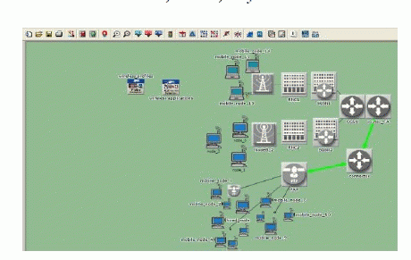
| We have used OPNET 14 to design and simulate the proposed integrated architecture of 802.11 WLAN and UMTS. |
| The proposed network elements of the designed architecture are given below: |
| • A 802.11a WLAN |
| • A 3G UMTS network |
| • A pilot access point (PAP) to which all the access points of the WLAN are connected. |
| • A connector (basically an IP router) between the two networks. |
| • A router attached to the GGSN that works as a foreign agent. |
| • Two pair of GRE tunnel between the foreign agent and the connector and between the PAP and the connector. |
| A. Configuration of Mobile IP in the Integrated Architecture |
| B.GRE Tunnel Configuration |
| One pair of GRE tunnels are configured Between the PAP and the connector.. RIP has been used as the routing protocol and IPV4 has been used the passenger protocol. |
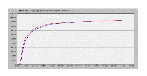
| Figure 7.16 shows UMTS GTP uplink and downlink graphs. From the graph we can see that the received traffic is increasing with the sent traffic up to 20 minutes of simulation time. After that a constant value is achieved. And the packet loss encountered is minor. |
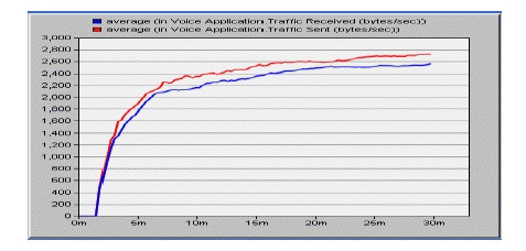
| Figure 7.17 shows the sent and received traffic for voice-over-IP application through UMTS. The above figure shows that the sent traffic is increasing with the received traffic. The maximum data rate achieved is 2.6 Kbps. |
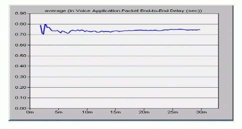
| Figure 7.18 shows the end to end packet delay for voice application. From the graph we can see that up to 8 minutes of simulation seconds the value fluctuates between 0.70 and 0.80 seconds. After that the value becomes constant. |
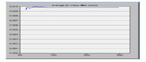
| Figure 7.19 shows the jitter for UMTS voice application. We can see from the figure that its value is almost constant (0.010 seconds). That means the user experiences a constant speed. |
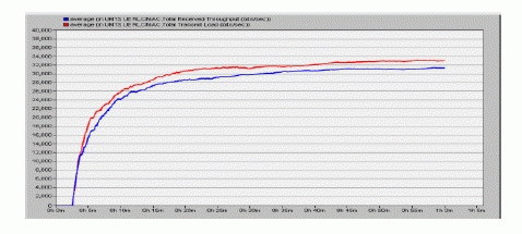
| Figure 7.20 shows the load and throughput of particular UMTS user equipment. From the graph we can see that the throughput is increasing with the load and the throughput achieves a maximum value of 30 Kbps. |
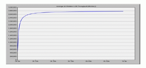
| The above figure shows the through put of 802.11a WLAN in the integrated network. From the graph we can see that the throughput is increasing up to 8 minutes of simulation seconds and after that it achieves a constant value. The maximum value of the throughput is almost 2.8 Mbps. |
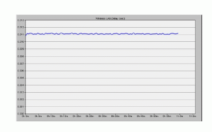
| Figure 7.22 shows the delay of WLAN in the integrated network. The figure shows the delay is almost constant and its value is 0.11 seconds. |
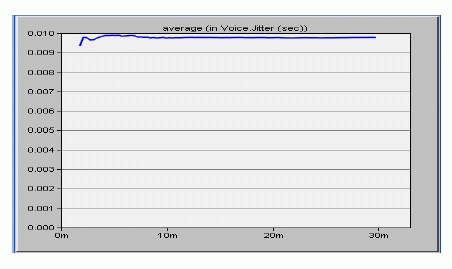
| Figure 7.23 shows the voice jitter of WLAN in the integrated network. The graph shows that it is almost constant and the average value is 0.010 second. |
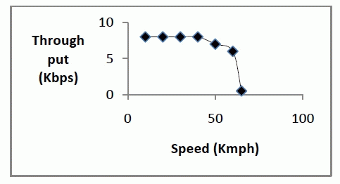
| Figure 7.24 shows, how the throughput of a mobile user changes with its increasing speed of movement. The graph shows that up to the speed of 40 Kmph the throughput remains constant. After that packet loss starts and the throughput reduces. Packet loss is largest at a speed of 65 Kmph. i.e. the maximum user speed WLAN can support is 60 Kmph in our integrated architecture. |
CONCLUSION
|
| Here we have introduced an integrated architecture of 802.11a WLAN and 3G UMTS networks. Through modeling and simulation we have shown that it can give speed up to 2.8 Kbps for cellular voice communication (real time traffic). The packet loss during the communication is very less. On the other hand, we have shown that the WLAN network can give throughout up to 2800 Kbps. For voice traffic, WLAN can give a speed of 85 Kbps with feasible delay and packet loss. In case of mobility, UMTS supports mobility over a wide range (Several kilometers) and WLAN supports mobility over a short range ( a few thousand square meters) |
| So, we can conclude that through this integration process we can utilize the advantages of both UMTS and WLAN. When a user needs high speed communication and his movement is over a short range, then he attaches to a WLAN and if a user has to move over a wide range of area and high speed communication is not a priority, then he attaches with UMTS. So, in this way we can get the advantage of ubiquitous (any time anywhere) connectivity in a heterogeneous environment. |
| Future Scope: |
| In our project we have used an IP router to connect WLAN and UMTS networks. A layer manager can be used in place of it for better functionality. We, therefore, plan to configure a layer manager in OPNET 14 for using in this architecture. We also include the analysis of call blocking probability of this integrated architecture in our future plan. |
ACKNOWLEDGMENT
|
| I want to express my gratitude to my guides Prof. Asish Kumar mukhopadhyay and Prof. Sajal Saha for their constant support and encouragement without which the completion of this work was not possible. |
Tables at a glance
|
|
|
| |
Figures at a glance
|
 |
 |
 |
 |
| Figure 1 |
Figure 2 |
Figure 3 |
Figure 4 |
 |
 |
 |
 |
| Figure 5 |
Figure 6 |
Figure 7 |
Figure 8 |
 |
 |
 |
 |
| Figure 9 |
Figure 10 |
Figure 11 |
Figure 12 |
|
| |
References
|
- Muhammad Jaseemuddin,“An architecture for integrating UMTS and 802.11 WLAN networks”, Proceedings of the Eighth IEEE InternationalSymposium on Computers and Communication (ISCC’03)
- Milindm.Buddhicot,”Design and implementation of a WLAN/CDMA 2000 interworking architecture”, IEEE Communications Magazine, Special Issue on 802.11 and 3G, Vol.41, No.11, Nov. 2003, pp.90-100
- Hyosoonpark,”Vertical handoff procedure and algorithm between IEEE802.11 wlan and cdma cellular network” Proceedings of the 7th CDMAinternational conference on Mobile communications,2003
- Massimo Bernaschi et al, “Seamless internetworking of WLANs and cellular networks: architecture and performance issues in a Mobile IPv6scenario”, Wireless Communications, IEEE, volume 12, issue 3, June, 2005.
- MeriemKassar,”a mobile-controlled handover management scheme In a loosely-coupled 3g-wlan interworking architecture”, wirelessdays,2008,1st IFTP
- Dianas.Deif, HadyaEi-Hennawy and Hesham EI-badaway,”Topology based modeling and simulation of UMTS-WLAN wirelessheterogeneous network”, proceedings of WOSN 2010 conference program Colombo, Srilanka
- Selvakumar.R,” Home Agent placement and assignment in WLAN withCellular Networks”, 2010 International Journal of Computer Applications (0975 – 8887), volume 1 -7.
- L.Ma et al,” New method to support UMTS/WLAN vertical handover using SCTP," IEEE Vehicular Technology Conference, vol. 3, 6-9 pp.1788-92, Oct. 2003
- Mi-Sun Do, Youngjun Park, and Jai-Yong, “Channel Assignment with QoS Guarantees for a Multi-Class Multi-Code CDMA System," Instituteof Electrical and Electronics Engineers, New York, NY, ETATS-UNIS, 2002, vol. 51, no5, pp. 935-948 [14 page(s) (article)].
- S. Khara, I.S Misra, D. Saha, “Improving Delay Performance in UMTS/WLAN Integrated Networks with Global Gateway Router”,Proceedings of IEEE 16th International Conference on Advanced Computing and Communications, Chennai, pp. 374-381, December 2008.
|