ISSN ONLINE(2319-8753)PRINT(2347-6710)
ISSN ONLINE(2319-8753)PRINT(2347-6710)
|
Vipin Chandra S PG Student, Department of Electronics & Communication Engineering, C.M.R.I.T, Bangalore, India |
| Related article at Pubmed, Scholar Google |
Visit for more related articles at International Journal of Innovative Research in Science, Engineering and Technology
CORDIC (Coordinate Rotation Digital Computer) algorithm is to be utilized on computerized workstations to execute complex scientific operations and trigonometric functions. This calculation has been utilized for proficient execution of vector rotation operations in hardware.In present day workstation frameworks (military frameworks, restorative provisions, and so on.) complex scientific operations and trigonometric counts are generally utilized. It is executed simply by table look-up, shift and add operations. In this study, two architectures called FPCORDIC and IQ-CORDIC have been conceived to actualize CORDIC calculation. These architectures have been acknowledged with IEEE-754 and IQ-Math number designs. Likewise they are contrasted concurring with execution time, process precision and fittings execution criteria on FPGA.
Keywords |
| CORDIC, FPGA, IQ-Math, IEEE-754 |
INTRODUCTION |
| In 1956, CORDIC (Coordinate Rotation Digital Computer) algorithm, found by Volder [6], was connected in numerous estimations, for example, trigonometric, linear, hyperbolic and logarithmic calculations. At present, the achievement of DSP calculations makes a solid impression, on account of FPGAs that have high performance and ability. This achievement gave the acknowledgment of numerous DSP algorithms on FPGA throughout the last a few years [1, 2, 3 and 4]. Today, the CORDIC algorithm is connected in the accompanying: digital signal processing, image processing, matrix algebra and so on. CORDIC algorithm acts as a cycle with the shift and add operations [7], it doesn't take much space on the hardware. In this way, it gives quick operation [7, 8]. |
| CORDIC construction modelling might be executed effectively in today's systems, however can't be utilized viably because of the way that systems are not ready to work parallel. FPGA's are fit for working in parallel, is frequently utilized as a part of requisitions empowering CORDIC algorithm which has an iterative structure to be realized adequately. |
| A structural configuration to help like CORDIC design having the capacity to prepare exact results and to work correspondingly while it is continuously executed on FPGA, must be conceived [6,9]. Advanced requisitions need exact and flexible computing necessities. CORDIC constructionmodelling can't be attained by a few advanced systems because of the computational load of the system needed. In spite of the fact that there are numerous CORDIC design created by utilizing FPGA, CORDIC architecture is to be implemented by utilizing the "IQ-Math" number system that Texas C28x DSP family firm runs or by utilizing the IEEE-754 "Floating-Point Numbers" so as to attain the prerequisite said above [10,11 ]. |
| The current form, IEEE 754 distributed in August 2008, incorporates about the majority of the first IEEE 754-1985 standard and the IEEE Standard for Radix-Independent Floating-Point Arithmetic (IEEE 854-1987). The IEEE Standard for Floating-Point Arithmetic (IEEE 754) is a specialized standard for floating-point processing made in 1985 by the Institute of Electrical and Electronics Engineers (IEEE). Various hardware floating point units utilize the IEEE 754 standard. |
| In this study, two architectures named FP- CORDIC and IQ-CORDIC has been contrasted agreeing with execution time, process precision and equipment execution criteria on FPGA. Second area gives data about the number format. In the third segment CORDIC algorithm and its working standard are specified. The fourth segment introduces that CORDIC algorithm implementation is focused on FPGA. Area five incorporates future scope and concludes of the work. |
RELATED WORK |
| CORDIC or Coordinate Rotation Digital Computer is a simple and hardware-efficient algorithm for the implementation of various elementary, especially trigonometric, functions. Instead of using Calculus based methods such as polynomial or rational functional approximation, it uses simple shift, add, subtract and table look-up operations to achieve this objective. The CORDIC algorithm was first proposed by Jack E Volder in 1959. It is usually implemented in either Rotation mode or Vectoring mode. In either mode, the algorithm is rotation of an angle vector by a definite angle but in variable directions. This fixed rotation in variable direction is implemented through an iterative sequence of addition/subtraction followed by bit-shift operation. The final result is obtained by appropriately scaling the result obtained after successive iterations. Owing to its simplicity the CORDIC algorithm can be easily implemented on a VLSI system. |
| For a long time the field of Digital Signal Processing has been dominated by Microprocessors. This is mainly because they provide designers with the advantages of single cycle multiply-accumulate instruction as well as special addressing modes. Although these processors are cheap and flexible they are relatively slow when it comes to performing certain demanding signal processing tasks e.g. Image Compression, Digital Communication and Video Processing. Of late, rapid advancements have been made in the field of VLSI and IC design. As a result special purpose processors with custom-architectures have come up. Higher speeds can be achieved by these customized hardware solutions at competitive costs. To add to this, various simple and hardware-efficient algorithms exist which map well onto these chips and can be used to enhance speed and flexibility while performing the desired signal processing tasks.One such simple and hardware-efficient algorithm is CORDIC, an acronym for Coordinate Rotation Digital Computer, proposed by Jack E Volder. |
| CORDIC uses only Shift-and-Add arithmetic with table Look-Up to implement different functions. By making slight adjustments to the initial conditions and the LUT values, it can be used to efficiently implement Trigonometric, Hyperbolic, Exponential functions, Coordinate Transformations etc. using the same hardware. Since it uses only shiftadd arithmetic, VLSI implementation of such an algorithm is easily achievable.FPGA provides the hardware environment in which dedicated processors can be tested for their functionality. They perform various high-speed operations that cannot be realized by a simple microprocessor. The primary advantage that FPGA offers is On-site programmability. Thus, it forms the ideal platform to implement and test the functionality of a dedicated processor designed using CORDIC algorithm. |
NUMBER FORMATS |
| IQ-Math number format: IQ-Math, fixed point number format utilized by the Firm Texas Instruments is indicated in Figure 1[1]. "S" denotes to the sign bit, "I" denotes to the integer place of the number and the fractional place of number is signified by 'Q'. If the sign bit is '0', the number is positive; else it is negative when the sign bit is '1'. Numbers are changed over into positive by taking two's complement. For instance, the change of the decimal number of 0.3 to the binary number system is shown below. |
| 0.3x0.2=0.6 0 |
| 0.6x0.2=1.2 1 |
| 0.2x0.2=0.4 0 |
 |
 |
| In equation (1) [1], 'N' denotes the real number, 'K' indicatesthe bit of integer place and the bit of decimal place is denoted by 'M'. |
| Addition:The signal flow outline of the IQ-Math number system addition is demonstrated in figure 2[1]. Additive function in this number format works as per the guidelines of the addition in binary format additive function. 'I' denotes the integer place and "Q" denotes the fractional place. In figure 2, integer place is showed on the left side, and decimal place is exhibited on the right side for each input. The 32-bit inputs are divided into two 24-bit and 8-bit numbers. At last, the carry that is gotten from the sum of the variables 'Q (Qcarry)' and 'I' variables values that is kept are added. The results, two variables called 'Ians' and 'Qans' are kept. Any overflow addition is not considered. Qans is of 24- bits and Ians is of 8-bits |
| Multiplication: Fundamentally IQ-Math number of the multiplication algorithm is the same fractional number multiplication. The signal flow chart of the IQ- Math number system multiplication is indicated in figure 3[1]. In multiplication, the numbers given as input to the biggest valence bit is checked. In the event that this bit is logically '1', the number is negative, otherwise positive. In the event that the number is negative, two's inverse of the number as indicated in figure 3 and it is made a positive number by adding ‘1’. Then multiply the two numbers in base-2 numeral system. Anyhow the number of 64-bit happens when the 32-bit two numbers in base-2 numeral system are multiplied. So that, 64-bit 'mc' register is kept as a result of the multiplication. Value in register two's complements if any of the numbers from the input is negative. At long last, the most significant of the 32-bit number to 64-bit number for calculations is taken and is given out as the output. |
| IEEE-754 Floating point number format: Realized with the extent of past studies, the IEEE-754 Floating-Point Number Format addition/subtraction and multiplication [13] is optimized and utilized as a part of this study. In equation (2) [1] floating-point number format is given. In this formula, it is exhibited that 's' demonstrates sign bit, 'e' indicates exponent of number and 'f shows multiplier expression. |
 |
| Unquestionably the number is resolved firstly by the addition of the floating-point numbers and the small number with the upper part of number synchronized as equations (3)[1]. |
 |
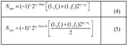
| The aggregate estimation of two decimal numbers summation is gotten as in equation (4)[1]. If the sum of multiples is greater or equal to 2,the total is written as in equation(5)[1]. Subtraction is like addition. |
 |
| Floating-point multiplication is given in equation (6)[1]. |
 |
| As on account of addition, if the whole of products is more than or equivalent to 2, the total is achieved like in equation (7)[1]. |
CORDIC ALGORITHM |
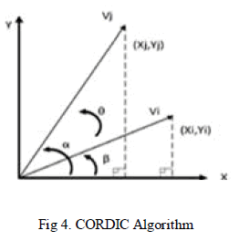
| CORDIC algorithm is a strategy for shifting the coordinate system of vectors until it is introduced at the angle between two vectors on the X-Y axis. The angle is computed by shifting and adding operations the X-Y axis. The operation mode of CORDIC algorithm is demonstrated in Figure 4[1]. |
 |
 |
| Angle value at each step can be calculated asfollows. The sum of all the angles in steps should give the angle of rotation θ. |
 |
| Here, Sn= {-1, + 1} and in accordance with the aboveequations, the value of tan θn is; tan θn = Sn 2-n. |
 |
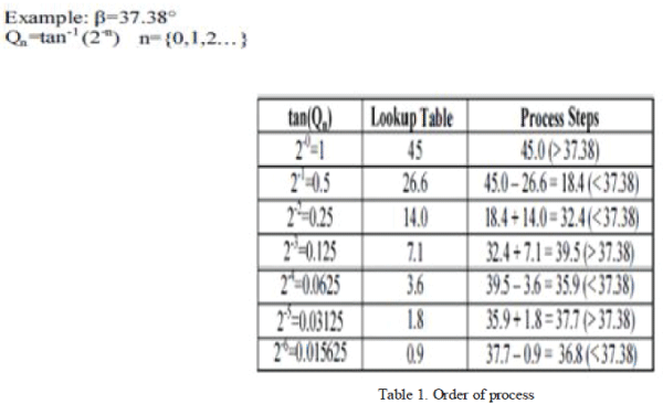
| An example of the operation mode of CORDIC Algorithm is shown in Table 1[1] briefly. |
 |
CORDIC IMPLEMENTATION ON FPGA |
| The main phase of realization of CORDIC Algorithm on FPGA is to focus the number format to be utilized by the system [10]. calculation of complex mathematical operations, for example, CORDIC normally needs a larger range of numbers. Besides, it is desirable over use floating-point numbers because of their dynamic representation [14]. On the other hand, in spite of their numerous preferences, provisions actualized with floating-point numbers work slower than the ones in fixed-point number. Likewise, requisitions realized with floating-point numbers format utilize a considerable amount of hardware resources of FPGAs [15]. In this study, CORDIC algorithm is tested with both number formats and the results are given in this area by correlation. The flow chart of the realization of a CORDIC algorithm on FPGA utilizing IQ-Math number format is shown in Figure 5[1]. |
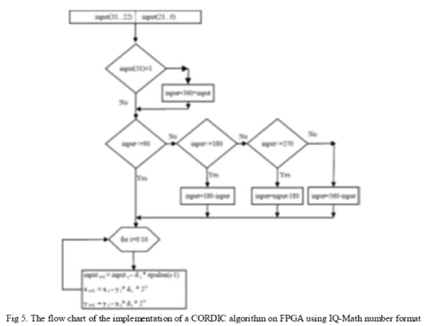 |
| To begin with, the plot is checked whether the value is positive. At that point, it is determined to which region the angle belongs in the x-y plane. Angle value is scrolled to the region I or region II, III or IV. At last, the angle value is compared with epsilon values in the lookup tables. As a consequence of the correlation, the coordinate estimations of the angle are gotten. The coordinate values are acquired by the formula given below: |
 |
| Here, d = +1 is taken if the input value is positive, otherwise it is taken as d = -1. |
| The results of the implementation of the CORDIC algorithmon FPGA using Floating-point and IQ-Math number formatand the part of values in Mat lab are shown in Table 2 (a), Table 2 (b) and Table 2 (c) [1]. |
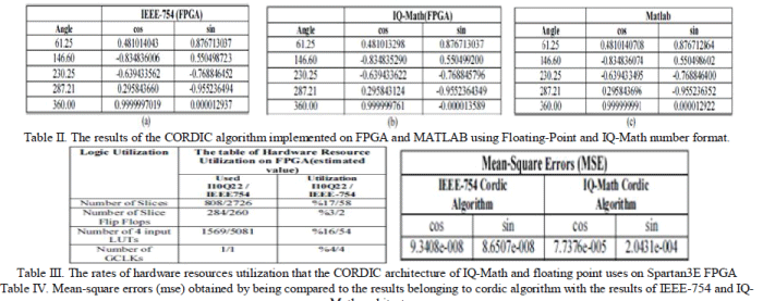 |
| As per the results acquired in the table 3[1] above the implementation of the CORDIC algorithm on FPGA utilizing Floating-point number format has produced more delicate results than IQ-Math number design. In the investigation of IQ-Math, process correctness is 2.3842E-007 while in the investigation of IEEE-754, methodology process accuracy is 1.4E-45. |
| Table 3 shows the results of synthesis FPGA module realized with I10Q22 number format and Floating-point number format. The application is created with Xilinx ISE 10.1 product and it is executed by utilizing a Xilinx Xc3s500e- 5fg320 FPGA chip which belongs to the group of Spartan 3E. |
CONCLUSION |
| Imperativeness of the number formats goes to the cutting edge when calculations like CORDIC including complex scientific operations are constantly realized [10]. As might be seen in Table 3, when compared with the floating-point number format, architecture realized with IQ-Math number format covers less space; hence, less resource are utilized on FPGA. Moreover, architecture implemented with IQ-Math number format gives quicker results in terms of preparing time when contrasted with the floating-point numbers. Yet as indicated in Table 4[1], the floating-point number format gives more exact results when contrasted with IQ-Math number format. |
References |
|