Keywords
|
| Sigma delta modulator, Signal to Noise Ratio ,Dynamic Range , Quantization Noise, Effective Number of Bits (ENOB) |
INTRODUCTION
|
| Modern society relies on signal processing. It is applied in communication equipment, medical devices, automated production facilities, computers, weapons, navigation equipment, tools etc.[1] The first step performed by a signal-processing system is to convert a considered signal into a form that can be processed by an electronic circuit. Sometimes a dedicated electro-mechanical system (called a sensor) will be required to sense the signal and convert it into a voltage, charge or current signal, and sometimes the signal is readily available in one of these forms. The signal processing that needs to be performed can vary from very simple operations (e.g. amplification) to extremely complex ones involving computation of several parameters, such as standard deviation, spectral composition, correlation coefficients, etc.[2] A fundamental property of analog electric signal processing is that each operation will be associated with a degradation of the signal-to-noise ratio (SNR). Hence, if substantial analog signal processing (ASP) is performed, stochastic artifacts (noise) will accumulate, and the resulting signal may not represent the desired signal with the required significance. This work focuses almost exclusively on delta-sigma modulation as chosen technique for A/D and D/A conversion. Based on the combination of oversampling and quantization error shaping techniques,[1] ΔΣMs achieve a high degree of insensitivity to analog circuit imperfections, thus making them a good choice (the best one in many cases) to realize embedded analog-to-digital interfaces in modern systems-on-chip (SoCs) integrated in nanometer CMOS[3]. Inspite of all the above mentioned advantages , this modulator have some practical issues and trade off related to power consumption, silicon area etc, which must be taken into account for optimized performance. The paper is organized as follows: Section II gives the overview of different blocks of SDM, Section III provides the realization of first order SDM, Section IV provides the SNR Limit for different order and different OSR, Section V provides the Conclusion on the basis of comparison. |
BUILDING BLOCK OF SIGMA DELTA MODULATOR
|
| A. Over Sampling |
| In signal processing, over sampling is the process of sampling a signal with a sampling frequency significantly higher than twice the bandwidth or highest frequency of the signal being sampled. Oversampling helps avoid aliasing, improves resolution and reduces noise. Oversampling is the process of increasing the sampling frequency by generating new digital samples based on the values of known samples. |
| Over sampling Factor: An oversampled signal is said to be oversampled by a factor of β, defined as |
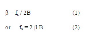 |
| where: |
| • fs is the sampling frequency |
| • B is the bandwidth or highest frequency of the signal; the Nyquist rate is 2B. |
| B. Quantization and Quantization Error. |
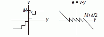
| Discretization in amplitude domain of any continuous signal is said to be Quantization. This continuous-to-discrete transformation in amplitude generates an error, commonly referred to as quantization error. The quantization itself introduces a fundamental limitation on the performance of an ideal ADC. It degrades the quality of the input signal whose continuous-value levels are mapped onto a finite set of discrete levels |
| Fig. 1(a) shows the transfer characteristic of an ideal quantizer, where e stands for the quantization error. This error is a nonlinear function of the input signal, as shown in Fig. 1(b). Note that, if x is confined to the full-scale input range [−XFS /2, XFS /2], the quantization error is bounded by [−Δ/2, Δ/2], with being the quantization step, defined as the separation between adjacent output levels in the quantizer. As long as the quantizer does not overload |e| ≤ Δ/2.The number of quantization levels is large, then the quantization noise is white with a power σe2 = Δ2/12 = 1/3 for Δ=2. |
| C. Noise Shaping |
| The accuracy of Oversampling ADC / DAC can be increased by applying methods to reduce quantization noise. A method in which the inband noise is pushed in the frequency out of interest. Such a phenomena is called Noise Shaping ,where the quantization error conceptually generated by the difference of the input signal, , from an analog version of the quantizer output, —is shaped by a filter with a transfer function, usually called noise transfer function (NTF), which can be either of high-pass type or band-stop type. In case low pass oversampled signal ,the low frequency inband component the removal of quantization Noise can be done through Differentiator in z domain transfer function is given by : |
| NTF (z) = (1 – z-1) L - (3) |
| Where L denotes the order of filter.[3] |
| D. Collectively: Sigma Delta Modulator |
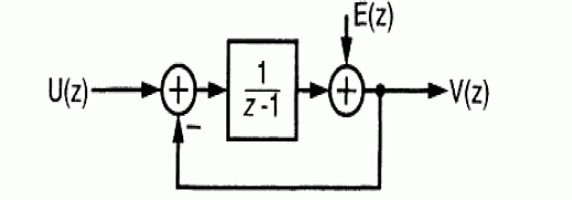
| A Sigma Delta Modulator contains feedback loop, containing a loop filter which is in the forward path of the loop. Replacing as before the quantizer by its linear model, the linear sampled-data system of Fig. results. |
| Analysis gives |
| v (n) = u (n-1)+e(n)-e(n-1). |
| Thus, the digital output contains a delayed, but otherwise unchanged replica of the analog input signal u, and a differentiated version of the quantization error e. the differentiation of the error e suppresses it at frequencies which are small compared to the sampling rate fS. In general, if the loop filter has a high gain in the signal band, the in-band quantization "noise" is strongly attenuated, a process now commonly called noise shaping. |
REALIZATION
|
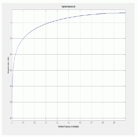
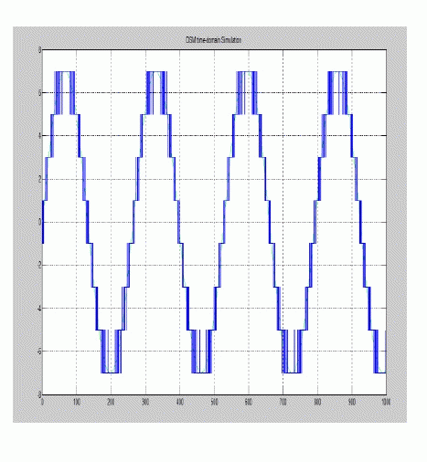
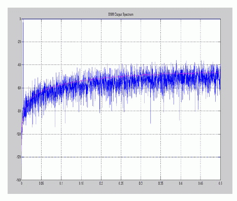
| First order Sigma Delta Modulator is realized using MATLAB [4],by providing the input parameters as OSR = 32, Quantization Level = 8 by the usage of specifically DelSig Toolbox. Figure 3 (a) shows the magnitude response of the NTF, Figure 3 (b) shows the Time domain analysis of SDM, Figure 3 (c) shows the Frequency domain analysis of SDM |
SNR LIMIT AND COMPARISON OF QUANTIZATION LEVELS
|
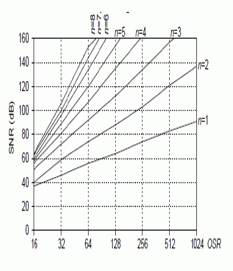
| For different order of filters ranging from n = 1 to n= 8with varying the OSR range from 16 to 1024, the graph is plotted to signify the SNR Limit. Figure 4 shows the variation of SNR with respect to varying OSR and order for binary low pass Sigma Delta Modulator. |
| As the quantizer and filter introduces error in the modulator and reduces SNDR. The signal-to-noise-plus-distortion ratio (SNDR) of the filter as the desired output signal power divided by the sum of the corresponding noise and distortion powers. Typical filtering applications require that the SNDR at the output of the filter be higher than a minimum specified value SNDR (spec). The range of signals over which the SNDR requirement is met is defined as the usable dynamic range (UDR) of the filter. |
CONCLUSION
|
| From the above survey, it is concluded that as the order of quantizer bit increases the peak SNR value can be achieved at lower OSR, after a certain level the increase in OSR will not affect the SNR value. Also, up to a specific level of quantization with the increase in OSR(at OSR = 8) ,the SNR suddenly increases, with increase in ENOB and increase in Quantization noise reduction. |
Tables at a glance
|
 |
 |
| Table 1 |
Table 2 |
|
| |
Figures at a glance
|
 |
 |
 |
| Figure 1 |
Figure 2 |
Figure 3 |
 |
 |
 |
| Figure 4 |
Figure 5 |
Figure 6 |
|
| |
References
|
- J.Rosa, âÃâ¬Ã⢠Sigma Delta Modulators : Tutorial Overview, Design Guide, and State of the Art Survey âÃâ¬Ãâ¢, IEEE Transaction on Circuits and System – I , Vol 58No. 1, pp 1- 2, January 2011.
- Schreier . R and Temes.G ,(Editor) âÃâ¬Ãâ¢Understanding Delta Sigma Data Converters ,Wiley Interscience Publication, United States of America, 2005.
- Norsworthy . S, Schreier . R and Temes.G ,(Editor), âÃâ¬Ãâ¢Delta Sigma Data Convereters,IEEE Press ,Wiley Interscience Publication, United States of America,1997.
- MATLAB Version 10, Sigma Delta Toolbox, www.mathwork.in
- Palaskas . Y et.al , âÃâ¬Ãâ¢A âÃâ¬Ãâ¢Divide and Conquer Technique for Implementing Wide Dynamic Range Continuous-Time Filters , IEEE Journal of Solid StateCircuits, Vol 39, Issue 2, pp.297 – 306, February 2004.
- Wang .T et.al. , âÃâ¬Ã⢠Analysis and Design of a Continuous-Time Time Sigma-Delta Modulator with 20MHz Signal Bandwidth, 53.6dB Dynamic Range and 51.4dB SNDR, IEEE International Symposium on Electronics Design,Test& Applications, pp . 74- 81, 2008.
- J. Silva, U. Moon, J. Steensgaard And G.C. Temes âÃâ¬Ãâ¢Wideband Low-distortion Delta-Sigma ADC Topology, Electronics Letters, IEEE Conference, Vol.37, Issue : 12 , pp 737-738, Jun 2001.
- Benoit Dufort And Gordon W. Roberts, âÃâ¬Ãâ¢Signal Generation Using Periodic Single And Multi-bit Sigma- Delta Modulated Streams, International TestConference, IEEE Conference, pp 396-405, November 1997.
- Ahmed Shahein, Mohamed Afifi, Markus Becker, NiklasLotze, and YiannosManoli, A Power-Efficient Tunable Narrow-Band Digital Front End forBandpass Sigma–Delta ADCs in Digital FM Receivers Circuits and Systems II: Express Briefs, IEEE Conference ,VOL. 57,Issue No. 11, pp 883 -887,November 2010.
- Mladenov .V, âÃâ¬Ã⢠A Method of Validation the Limit Cycles of High order Sigma Delta Modulator, Nonlinear Dynamics and Synchronization (INDS) and16th International Symposium on Theoritical Electrical Enggineering, pp 1-5 ,25-27 July.
- Philippe Benabes1, Ali Beydoun2, MohamadJavidan, âÃâ¬Ãâ¢Frequency-band-decomposition Converters Using Continuous-time Sigma-Delta A/D Modulators,Circuits and Systems and TAISA Conference, IEEE Conference, pp 1-4, July 2009.
- MichatSzermer, Marcin Daniel, AndrzejNapieralski, âÃâ¬Ãâ¢Modeling and Simulation Sigma-Delta Analog to Digital Converters using VHDL-AMS, CADSM2003. The Experience of Designing and Application of CAD Systems in Microelectronics. Proceedings of the VIIthInternational Conference, IEEE Conference,pp 331 -333, February 2003.
|