Keywords
|
| Microstrip Patch Antenna, Return Loss, Smith Chart, STM (Synchronous Transport Module). |
INTRODUCTION
|
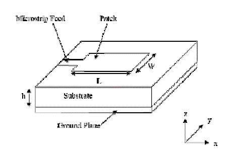
| Microstrip antennas have contributed a lot to the growth of antenna technology due to its salient features. This form of antenna has been utilized in various applications for example, in satellite communication, in handsets and base stations for mobile communication, in telemetry antennas for missiles and so on. Antenna is defined as a device or a transducer which transforms an RF signal into electromagnetic waves. It acts as a means to transmit and receive radio waves. Microstrip antennas cover a broad frequency spectrum from 100 MHz to 100 GHz, thus possess several advantages as compared to conventional antennas such as low profile, simple and inexpensive to design and manufacture, flexible in terms of configuration, polarization, pattern, resonant frequency and impedance when a particular shape and mode are selected [1]. Other advantages include robustness when mounted on rigid surfaces, easily fabricated on linear as well as planar arrays, integration with microwave integrated circuits and compatibility with MIMC design. A microstrip antenna consists of a conducting patch of any geometry on a ground plane and separated by a dielectric substrate. The rectangular and circular patches are most common geometry used in microstrip antennas. Rectangular patches are chosen as they are very simple to analyse and circular patches are chosen due to their symmetric radiation pattern. Various mathematical models have been developed for these antennas and the papers and articles published on them show their popularity among researchers [2]. |
RELATED WORK
|
| A microstrip patch antenna consists of a conducting patch on a ground plane and both are separated by a dielectric substrate. The revolution in electronic circuit miniaturization and large-scale integration led to the development of this concept in 1970. Afterwards, many authors described the radiation from the ground plane by a dielectric substrate for various configurations. The early work of Munson on micro strip antennas for use as a low profile flush mounted antennas on rockets and missiles showed that this was a practical concept for use in many antenna system problems. Various mathematical models were developed for this antenna and its applications were extended to many other fields. The number of papers, articles published in the journals for the last ten years, on these antennas shows the importance gained by them. The micro strip antennas are the present day antenna designer’s choice. Among the first two models were the Transmission line model and Cavity model. Both approaches are relatively easy to implement into a computer program and require relatively short computation time. However, with these models the antenna characteristics are not very accurate and are usually limited to the case of narrow band microstrip antennas (P. Bhartia, 1980). Later more accurate methods have been proposed such as Full Wave Analysis, FDTD and MPIE. In these methods, the antenna characteristics can be determined by solving the integral equations (method of moment). The integral equation method are not restricted to the case of single microstrip patch antenna but can also be applied to microstrip array and to multilayer configuration. However, a major drawback of these methods is long computation time and the relatively large computer memory requirements (Kin-Lu Wong, et al, 2001) [3]. |
SYSTEM MODEL AND ASSUMPTIONS
|
| Microstrip patch antenna consists of two parallel conductors – a thin metallic patch and the ground plane, which are separated by dielectric substrate. The patch can take any geometry i.e. rectangular, circular, elliptical, triangular or dipole but rectangular patch is used as it is easy to analyze. This patch when excited in fundamental mode gives pattern maximum and maximum directivity normal to the patch i.e. broadside [4]. Thick substrates having low value of dielectric constant are preferred for good antenna performance in terms of efficiency, bandwidth, and radiation pattern but at the cost of element size. For microwave circuitry, thin dielectric substrates having higher value of dielectric constant are used due to tightly bound fields of radiation but the efficiency and bandwidth are relatively lesser. |
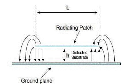
| Radiation in Microstrip antenna occurs from the fringing fields existing at the open circuited end or edges of the patch. The fringing fields at the two open circuited ends of the patch can be resolved into two components; one normal to the ground plane and other parallel to the ground plane. The normal electric fields are out of phase and hence radiation due to these components cancels in far region. However the radiation fields due to tangential components of electric fields being in phase add together in far zone in the broadside direction. Thus the maximum radiation due to Microstrip patch is in the broadside direction [5]. |
| The microstrip antenna using transmission model is designed in the following method: |
Step 1: Calculation of the Width
|
| For an efficient antenna, a practical width that leads to good radiation efficiency is given by eqn. (4), |
 (4) (4) |
| Step 2: Calculation of the effective dielectric constant (ereff) |
| The effective dielectric constant is given by eqn. (5), |
 (5) (5) |
Step 3: Calculation of the length extension
|
| The normalized extension of length is given by eqn. (6), |
 (6) (6) |
Step 4: Calculation of the length of patch
|
| The actual length of patch can be determined by eqn. (7), |
 (7) (7) |
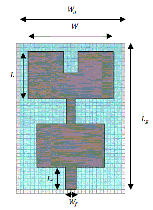
| The length Lg and width Wg of ground is given by: |
 (8) (8) |
 (9) (9) |
ANTENNA DESIGN
|
RESULTS AND DISCUSSION
|
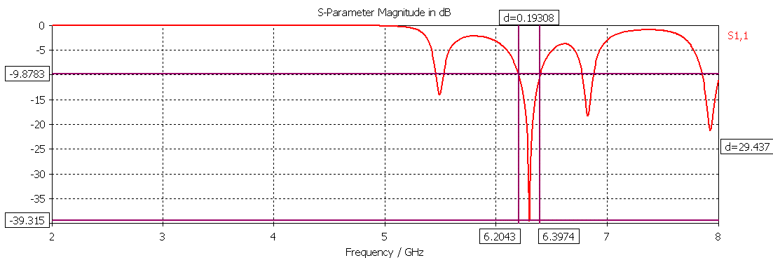
| Tri-band has been achieved in this design. The first band has resonant frequency 5.5 GHz and bandwidth 66 MHz with return loss -12.95. This frequency range is used for Wi-MAX applications. The resonant frequency of second band is 6.3 GHz and bandwidth is 190 MHz with return loss -30.56. The third band has resonant frequency 6.8 GHz and bandwidth is 102 with return loss -16.72. This second and third band is suitable for wireless application of STM link 1 (Synchronous Transport Module level 1).The plot of return loss against frequency is shown in Figure 4. |
A. Smith Chart
|
| Smith Chart was invented by Philip H. Smith to solve the problems of transmission lines and matching circuits. The three circles in the smith chart represent the frequencies of the triple band. |
B. Gain
|
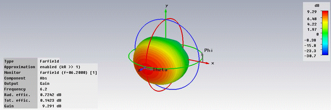
| Gain of an antenna gives the measure of the efficiency of the antenna and its directional capabilities. Gain is defined as the ratio of radiation intensity in a particular direction to the radiation intensity obtained if power is radiated isotropically by that antenna [6]. The gain should be greater than 5dBi and in this case it is found to be 9.291 dBi which is very useful for Wi-MAX and STM (Synchronous transport module level 1) applications for providing a better performance. The plot of 3D view of Gain at 6.2 GHz is shown in Figure 6. |
C. Directivity
|
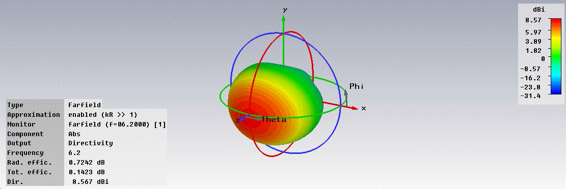
| Directivity of an antenna is defined as the ratio of radiation intensity of antenna in a given direction to the radiation intensity of that antenna averaged over all directions and it is dimensionless. The directivity should be greater than 5dBi [7]. The directivity plot as shown in Figure 7 represents amount of radiation intensity i.e. is equal to 8.567 dBi which is acceptable for a good performance of the antenna. |
D. Current Distribution
|
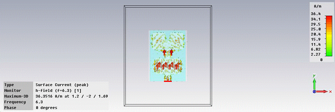
| The current should be maximum at the centre of the patch and minimum at the edges, which has been obtained in this design. The current distribution of the proposed design is shown in Fig. 3.9. The current distribution basically represents the current intensity [8]. |
ANTENNA OPTIMIZATION
|
A. Effect of varying Stub Length
|
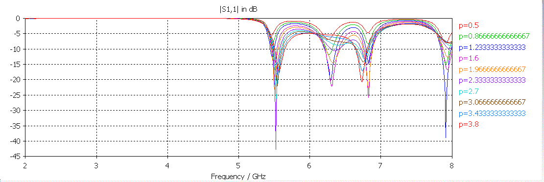
| Feed line should be chosen in such a way so that there is a good impedance match between the generator impedance and the input impedance of the patch element [9]. For maximum coupling, it should be placed perpendicular to the slot. [] As from the Figure 9, it can be seen that as a feed length is increased, the return loss is decreased from -5.5dB to - 42dB till 2.3mm and then again increased to -16dB. So for proper matching, the stub length chosen is 2.3mm with return loss of -42dB and Stub length equal to 2.85mm is considered for design of this antenna. |
B. Effect of varying Patch Length
|
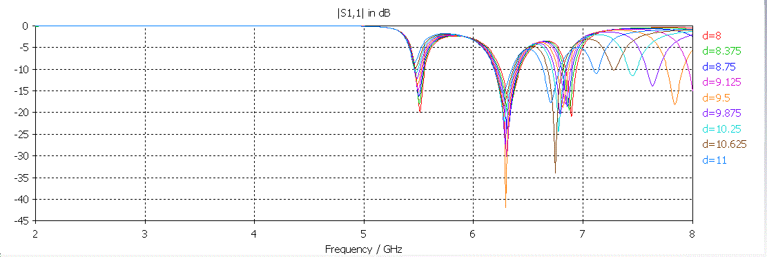
| On increasing the length of patch antenna, the resonant frequency moves towards the lower band and on decreasing the patch length the resonant frequency moves towards upper band. Maximum coupling will be obtained when patch is at the centre [10]. The length of lower patch is varied and the return loss decreases as the length of patch is increased upto 9.5 mm and then starts increasing. Thus, the length is taken 9.5 to obtain return loss of -41.5 dB. |
CONCLUSION AND FUTURE WORK
|
| A triple band microstrip patch antenna with microstrip feeding technique has been successfully designed according to design specifications, simulated and analysed. The design of this work gives the following results; The first band has resonant frequency 5.5 GHz and bandwidth 66 MHz with return loss -12.95. This frequency range is used for Wi-MAX applications. The resonant frequency of second band is 6.3 GHz and bandwidth is 190 MHz with return loss -30.56. The third band has resonant frequency 6.8 GHz and bandwidth is 102 MHz with return loss -16.72. This second and third band is suitable for wireless application of STM link 1 (Synchronous Transport Module level 1).The VSWR obtained is 1.061. The performance of the antenna meets the desired requirements in terms of return loss and VSWR at the desired operating frequency. Although, it can be designed using IC fabrication and can be tested using Network Analyser. The antenna will be fabricated using PCB technology and will be tested in anechoic chamber and vector network analyser. |
Tables at a glance
|
 |
| Table 1 |
|
| |
Figures at a glance
|
 |
 |
 |
 |
 |
| Figure 1 |
Figure 2 |
Figure 3 |
Figure 4 |
Figure 5 |
 |
 |
 |
 |
 |
| Figure 6 |
Figure 7 |
Figure 8 |
Figure 9 |
Figure 10 |
|
| |
References
|
- Theodore S. Rappaport, “Wireless Communications and Practice”, 2nd Edition, 2009
- Constantine A. Balanis , “Antenna theory Analysis and Design”, 2nd edition, John Wiley and Sons, 2009
- Kin-Lu Wong, Wen-Hsiu Hsu, “A Broad-band Rectangular Patch Antenna with a Pair of Wide Slits”, IEEE Transactions on Antennas andWireless Propagation, vol. 49, pp. 1345- 1347, 2001.
- J. D. Kraus, R.J. Marhefka, “Antennas for all applications”, Tata McGraw Hill Edition, 2003.
- Stephen D. Targonski and David M. Pozar, Fellow, “Design of Wideband Circularly Polarized Aperture-Coupled Microstrip Antennas”IEEE Transaction on Antennas and Propagation, Vol. 41, No. 2, pp. 214-220, Feb 1993.
- D. M. Pozar, “A Review of Aperture Coupled Microstrip Antennas: History, Operation, Development, and Applications”, 1996.
- S. Maci and G. BifJi Gentili, “Dual Frequency Patch Antenna”, IEEE Antennas and Propagation Magazine, vol. 39, no. 6, pp. 13-20,1997.
- Naftali Herscovici, “A Wide-Band Single-Layer Patch Antenna”, IEEE Transaction on Antennas and Propagation, vol. 2, no. 4, pp.1108-1111, 1998.
- S.K. Palit, A. Hamadi, “Design and development of wideband and dual-band microstrip antennas”, Microwaves, Antennas and Propagation,IEEE Proceedings, vol. 146, no. 1, pp 35 – 39, Feb 1999.
- Y. -L Kuo, Kin-Lu Wong, “Printed Double T-Monopole antenna for 2.4/5.2 GHz Dual-bend WLAN Operations”, IEEE Transactions on Antennas and Wireless Propagation, Vol. 51, No. 9, pp. 2187-2192, Sept. 2003.
|