Keywords
|
| Wind generator, High frequency transformer, AC-AC converter, multilevel inverter |
INTRODUCTION
|
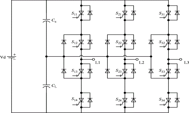
| Renewable energy has been appreciated as alternative resources for electric power generation. Installations of renewable energy have continued growing dramatically around the world. The network side NPC converter controls real and reactive power flow to the network and thus regulates the DC bus voltage and the AC side power-factor respectively [1]. Distributed Power Generation Systems based on renewable energy sources experience a large development worldwide. Due to the increasing number of DPGSs connected to the utility network new and stricter standards in respect to power quality, safe running and islanding protection are issued. As a consequence, the control of distributed generation systems should be improved to meet the requirements for grid interconnection [2]. AC–AC converter to generate a high-frequency current for Inductive Power-Transfer systems. Unlike traditional DC–AC converters for IPT systems, the proposed converter can achieve a high-frequency current generation directly from an ac power source without a DC link [3]. |
| The specification of a power electronic interface is subject to requirements related not only to the renewable energy source itself but also to its effects on the power-system operation [4]. This paper proposes to replace the input diode-based frontend rectifier with an active front-end rectifier in all cells of the topology and a novel control strategy in order to overcome the drawbacks [5]. The main advantage compared to cascaded multilevel converters is the lack of an input transformer which results in a reduction of cooling requirements, size, and cost. One of the drawbacks of this topology when used as an AC–AC converter is the input and output frequency components in the control loop resulting in a more complex controller design [6]. The renewable energy sources cannot be connected to the grid directly. These topologies are able to synthesize higher number of output voltage levels which makes it possible to reduce the voltage and current harmonics applied to the grid. The requirements for the grid connected power converter can be listed as follows: |
| I. Galvanic isolation between the grid and the energy sources for protection and safety. |
| II. Control of reactive power transfer between the grid and the energy sources. |
| III. High quality of the injected power into the grid. |
| In this paper, new trends in power electronics for the integration of wind power generators are presented. It is expected that current developments in gearless energy transmission with power-electronic grid interface will lead to a new generation of quiet efficient and economical. These characteristics of the proposed power converter result in the reduction of the system volume and weight remarkably. The proposed AC-AC converter for wind energy system will be analyzed using the simulation result. The Neutral Point Clamped converter and the flying capacitor converter are well known in this field. The number of the output voltage level is limited for practical applications because of the many issues, such as complexity of the structure and difficulty of the regulation of the DC-link capacitor voltages. |
| To overcome the issues related to the reactive components and to connect the power converter to the grid directly. The volume and the weight of the converter can be reduced. A Dual Active Bridge converter was introduced at first in, and this topology has been used widely in high-power DC–DC converters owing to its advantages of high-power density, isolation characteristic, bidirectional power transfer capability, and modular and simple structure. |
| Multilevel inverters take a very fast development in high power medium voltage AC drives. Various type of topologies have found in industrial applications neutral point clamped multilevel inverter, flying capacitor multilevel inverter, Hbridge multilevel inverter with separate DC source, several control and modulation techniques are developed such as pulse width modulation, sinusoidal PWM, space vector PWM and selective harmonic elimination. |
| A. The Calculation for the Wire-Diameter |
| The wire-diameter depends on the respective R.M.S. value of the coil current. This can be calculated from the coil power. If the losses are neglected and it is assumed that with Vin_min the maximum duty cycle is achieved it follows that: For the Single Transistor Forward Converter: |
 (1) (1) |
| For the Full Bridge Push-Pull Converter: |
 (2) (2) |
| For the Half Bridge Push-Pull Converter: |
 (3) (3) |
| The wire cross-section Awire and the wire diameter dwire can be calculated as follows: |
 (4) (4) |
| Usual cores are designed such that the above calculated coil fits into the available winding area. Primary and secondary windings both need an equal amount of the winding area. |
PROPOSED METHOD
|
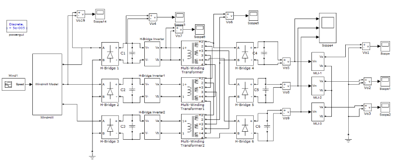
| Here the explanation of the block diagram was discussed with various components such as H-bridge inverter, high frequency transformer and bidirectional rectifier as shown in fig.2. As fossil fuel prices soar and environmental issues are concerned, the installations of renewable energy have continuously growing dramatically around the world. The output power, voltage, and frequency of the wind turbine depend on the speed of wind, which fluctuate over time and cannot be forecasted accurately so we are going with variable speed wind system. |
| A. Block Diagram |
| The input AC supply from win generator was converted into DC supply; again the H-bridge converter-1 converts the DC supply converted into AC supply. The converted AC is applied to the primary side of the high frequency transformer. Then the secondary side AC is applied to the converter-2, here the AC supply was converted into DC supply. H–bridge converter-2 converts the DC supply into AC supply and the converted AC supply was feed into the grid. |
| B. Grid to Wind Generator |
| During the bi-directional operation at the secondary side AC supply from grid was applied to H-bridge converter-2, here the AC supply was converted to DC supply. The DC supply was converted to AC supply in the Converter-2 then applied to the converter-1 through the high frequency transformer. H-bridge Converter-1 converts AC-DC supply. The DC supply was converted into AC supply by the converter-1and supplied to the wind generator. The filter capacitors in the grid side help distribute the phase voltage evenly across the stages, if the multiple stages are connected in series. Simulation diagram circuit is shown in Fig.3. |
| The capacitors also function as input filter along with filter inductance to suppress the high-frequency current ripples coming from the sine-modulated full-bridge inverter. The switches of the low-frequency bidirectional rectifier are switched synchronously with the line frequency and the switching loss of the low-frequency bidirectional rectifier is negligible. The sine-modulated full-bridge inverter and the high frequency bidirectional rectifier are connected to the high frequency multi winding transformer. The switching frequency of H-bridges in this part can be set up to 10 kHz considering the capacity of the existing switching devices. |
| The size of the transformer used in this converter was much smaller than that of conventional line-frequency transformers used in other topologies. The transformer has one winding on the primary side and multi winding on the secondary side. The number of windings on the secondary side was determined by the number of phases of the output side. The secondary winding of the transformer are connected in series, which makes the voltage applied to the high-frequency bidirectional rectifier the sum of the primary side voltages. The power transferred through one transformer can be constant under the assumption of the balanced load. |
SIMULATION RESULT
|
| A. Output Waveform of Wind Turbine |
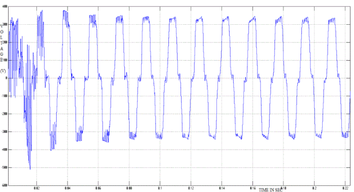
| The voltage obtained from the PM wind generator was about 350 volts as shown in the Fig.4 and it was given to the H-bridge converter. Initially it gets oscillated and then come to a study condition. |
| B. Output Waveform of The Inverter Circuit |
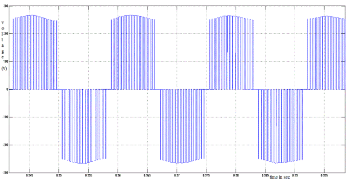
| The Fig.5 shows the output wave form of inverter. Based on the frequency of the inverters operation the output can change. |
| C. Output Waveform of High Frequency Transformer |
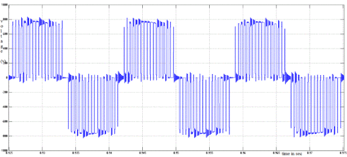
| The Fig.6 shows the output waveform of high frequency transformer. |
| D. Output Voltage Ac-Ac Converter With Grid Connected System |
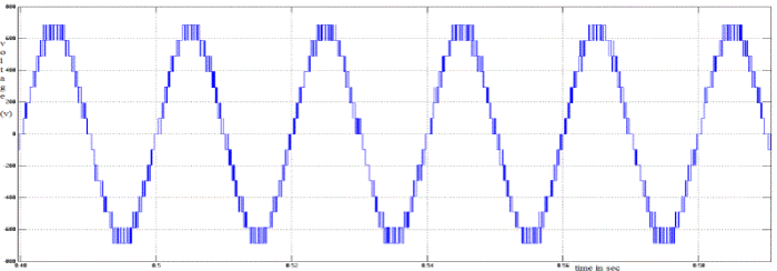
| The Fig.7 shows the output wave form of AC-AC converter. Initially the output takes some minimum time for getting settled. |
TOTAL HARMONIC DISTORTION
|
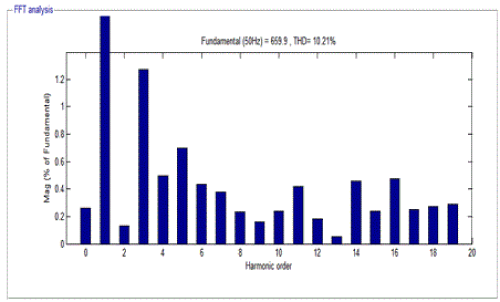
| The proposed circuit consists of H-bridge switches and for the harmonic reduction selective harmonic elimination technique is employed. |
| Form the Fig.8 it is clearly shown that the harmonics are very much reduced. The THD level estimated as 10.21% for the output voltage from the proposed H-bridge multilevel inverter. |
CONCLUSION
|
| In this project fifteen level h-bridge multilevel inverter is used to get sinusoidal waveform and also increase the efficiency of the inverter. The inverter cell is low means the design of inverter switch is easiest. Multilevel inverter is to obtain a high resolution. This inverter produces high output level using the reduced number of switches and low switching losses. The harmonic reduction is achieved to a greater extent than the other conventional inverters. The output phase to phase voltage is achieved. The technique is used to improve the level of inverter and design flexibility and reduces harmonics. The proposed control schemes have been verified analytically and demonstrated through simulation. In future the AC-AC converter simulation work is done by using MATLAB/SIMULINK and genetic algorithm, simulation results are analyzed. In future the simulations of AC-AC converter work changes the real time model and compare the results of real time model with the simulated design. |
| |
Figures at a glance
|
 |
 |
 |
 |
| Figure 1 |
Figure 2 |
Figure 3 |
Figure 4 |
 |
 |
 |
 |
| Figure 5 |
Figure 6 |
Figure 7 |
Figure 8 |
|
| |
References
|
- AmirnaserYazdani and Reza Iravani“A Neutral-Point Clamped Converter System for Direct-Drive Variable-Speed Wind Power Unit” IEEE Transactions on Energy Conversion, Vol. 21, No. 2,pp.596-607, (2006).
- Fredeblaabjerg, Remusteodorescu, Marcoliserre, and Adrian V. Timbus“Overview of Control and Grid Synchronization for Distributed Power Generation Systems” IEEE Transactions on Industrial Electronics, Vol. 53, No. 5,pp.1398-1409, (2006).
- Hao Leo Li, Aiguo Patrick Huand Grant Anthony Civic “A Direct AC–AC Converter for Inductive Power-Transfer Systems” IEEE Transactions on Power Electronics, Vol. 27, No. 2,pp.661-668, (2012).
- Juan Manuel Carrasco, Leopoldo Garcia Franquelo, , Jan T. Bialasiewicz,And Eduardo Galván“Power-Electronic Systems for the Grid Integration of Renewable Energy Sources” IEEE Transactions on Industrial Electronics, Vol. 53, No. 4,pp.1002-1016, (2006).
- Marcelo A. Pérez, José R. Espinoza, José R. Rodríguez And Pablo Lezana“Regenerative Medium-Voltage AC Drive Based On A Multicell Arrangement with Reduced Energy Storage Requirements” IEEE Transactions on Industrial Electronics, Vol. 52, No. 1,pp.171-180, (2005).
- Marcelo A. Perez, Jose Rodriguez, Esteban J. Fuentes and Felix Kammerer“Predictive Control of AC–AC Modular Multilevel Converters” IEEE Transactions on Industrial Electronics, Vol. 59, No. 7,pp.2832-2839, (2012).
- Myoungho Kim, Anno Yoo, and Seung-Ki Sul“A New Universal Isolated Converter for Grid Connection” IEEE Transactions on Industry Applications, Vol. 48, No. 2,pp. 685-696, (2012).
- Shigenori Inoue and Hirofumi Akagi“A Bidirectional DC–DC Converter for an Energy Storage System with Galvanic Isolation” IEEE Transactions on Power Electronics, Vol. 22, No. 6,pp. 2299-2306, (2007).
- Shigenori Inoue and Hirofumi Akagi“A Bidirectional Isolated DC–DC Converter as A Core Circuit of the Next-Generation Medium-Voltage Power Conversion System” IEEE Transactions on Power Electronics, Vol. 22, No. 2,pp.535-542, (2007).
- Siyoung Kim, Seung-Ki Sul and Thomas A. Lipo“AC/AC Power Conversion Based On Matrix Converter Topology with Unidirectional Switches” IEEE Transactions on Industry Applications, Vol. 36, No. 1,pp. 239-145, (2000).
|