Keywords
|
| Passive methods, Active noise controlling (ANC) technique, Digital Signal Processor (DSP), Field Programmable Gate Array (FPGA), least mean square (LMS) |
INTRODUCTION
|
| Noise has always been a nuisance to environment causing many types of losses in our day to day life. Thus the need of a smaller better and efficient noise control technique arose. [9] Satisfying this need Lueg proposed an technique of Active Noise Control, superimposing the sound waves to cancel them out. Many of the researchers have developed the techniques to implement this concept and also verified it.[11] |
| The passive techniques available work only on low frequencies noise i.e., up to 1000Hz.[14] |
| Active Noise Control works on the principle of destructive interference between sound-fields generated by the original (primary) source and the secondary sources, whose acoustic output is governed by a controller. The sound wave in the closed formation or structure can be considered as 1–D propagating wave, if the wavelength is longer than the structure.[4]. |
| ANC allows generating a zone-of-quiet based on destructive interference. The size and shape of this zone-of-quiet depend on the type of the sound sources and the frequency components of the signal to be cancelled [12]. |
| It is therefore possible to determine the performance of the scheme described in [10] at any point in the ear canal, based on the spatial distribution of the sound sources and on the position of the ear canal microphone. Formatter will need to create these components, incorporating the applicable criteria that follow [9]. |
BLOCK DIAGRAM IMPLEMENTATION OF THE SYSTEM
|
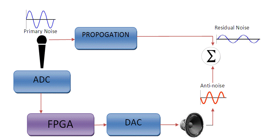
| The block diagram of Active Boise control is shown in fig. The noise control needs a high degree of speed and accuracy of operation. So we indent to implement this system on FPGA to achieve these parameters. The noise signal that is to be removed is taken as an input to the system by using a microphone and converted into a digital format using the fastest possible ADC available. Then the digitized signal is processed by using FPGA to invert and produce an exact replica of the input signal but in 180? phase shift. Then the digitized inverted signal is reproduced in the analog form by using the fastest possible DAC (Digital to Analog Converter) available. The signal so produced and the original signal are superimposed on each other. As the reproduced signal is opposite phase of the input signal, it gets added to the input signal and cancels it out. Thus, it leads to the suppression of the unwanted noise signal. |
TOPOLOGIES OF IMPLEMENTATION OF ANC
|
| Active noise control (ANC) can result in a large amount of noise reduction when it is of low frequency. At low frequencies, when only plane wave propagation is allowed, ANC offers a great advantage over passive technique .ANC systems are based on following two methods. |
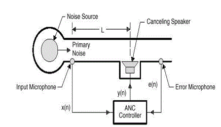
| • Feed forward control: Here, the input noise reference is sensed before it propagates to the cancelling speaker. |
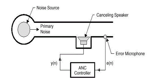
| • Feedback control: Here, the controller cancels the noise without the benefit of upstream reference noise [7]. |
| In this paper we are concentrating on feedback control of the ANC.In an ANC application, the primary near-end noise As d(n) is not available during the operation of ANC because it was cancelled by the secondary noise. Therefore, the basic idea of an Adaptive feedback ANC (AFANC) is to estimate the primary noise, and use it as a reference signal x(n) for the ANC filter, W(z).]Unlike an adaptive feed-forward ANC system, where a separate sensor is available to pick up the reference signal, the AFANC regenerates its own reference signal. An AFANC system is required for applications include spatially incoherent noise generated from turbulence; noise generated from many sources, and propagation paths, and induced resonance where no coherent reference signal is available in such a situation the speed deals with all the above issues involved in the ongoing process of noise cancelling.[13]. |
METHODS OF IMPLEMENTATION OF ANC
|
| There are basically two ways in implementing ANC. Firstly using an analog approach and secondly, using a digital approach. Let us get acquainted with both the approaches. |
A. ANALOG DOMAIN
|
| As a technology, analog is the process of taking an audio or video signal and translating it into electronic pulses. Analog technology has been around for decades. It's not that complicated a concept and it's fairly inexpensive to use. The trouble is, analog signals have size limitations as to how much data they can carry. |
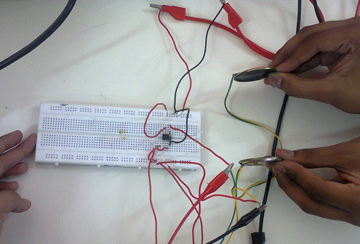
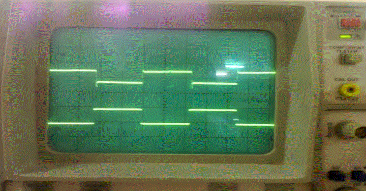
| The simplest way to build up an ANC circuit is using an op-amp 741 IC. The configuration is very simple, by applying a fixed frequency wave at the input. The op-amp is used in an inverting mode configuration with gain of 1. |
| Speakers are attached at the input and the output terminal that would produce the noise signals. Now both the noises are superimposed to cancel out. |
| The main disadvantage of using this system is the slow processing, which leads to delay in superimposing the two signals. |
B. DIGITAL DOMAIN
|
| Digital on the other hand is breaking the signal into a binary format where the audio or video data is represented by a series of "1"s and "0"s. The beauty of digital is that it knows what it should be when it reaches the end of the transmission. That way, it can correct any errors that may have occurred in the data transfer. The different ways of building an ANC circuit in digital domain are: |
B.1. USING MICROCONTROLLER
|
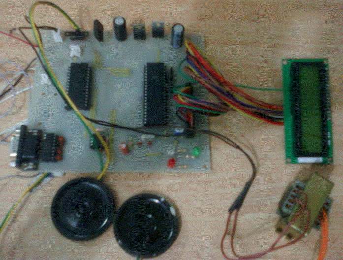
| Microcontrollers are special types of processor chips that are very small and somewhat versatile, due to their programmable nature. This type of processor is fully integrated, a "computer on a chip”. We can build ANC circuit using ADC & DAC circuits interfaced with microcontroller. For the same purpose we had used ADC0808 and DAC 0809 interfaced with Atmel’s Atmega16 .The processing speed is somewhat greater than using an op-amp, but still the delay occurs in super positioning of the original and the inverted signal. |
B.2. USING DIGITAL SIGNAL PROCESSOR (DSP)
|
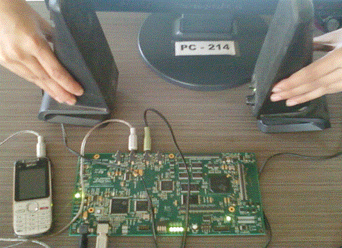
| Digital signal processing allows sounds to be recorded and transmitted in ways not possible through previously used analog technology. Programming a DSP is similar to programming any other type of microcontroller, except that it is designed with signal processing in mind. As such it is designed with extra multipliers and pipelines to allow faster signal processing. For this purpose we had used TMS320C6713 DSP kit. |
| Signal processing is done by AIC23 codec which is acting as both ADC and DAC. AIC23 use ADC & DAC of multi bit sigma-delta technology with integrated oversampling digital interpolation filters. Data-transfer word lengths of 16, 20, 24, and 32 bits, with sample rates from 8 kHz to 96 kHz, are supported. |
Features and Specifications
|
| • Highest-Performance Floating-Point Digital |
| • Signal Processor (DSP) |
| • Eight 32-Bit Instructions/Cycle |
| • 32/64-Bit Data Word |
| • 225-, 200-MHz (GDP), and 200-, 167-MHz |
| • Two ALUs (Fixed-Point) |
| • Four ALUs (Floating- and Fixed-Point) |
| • Integrated Digital Audio Interface Transmitter (DIT) |
| • Dedicated GPIO Module With 16 pins (External Interrupt Capable) |
| • IEEE-1149.1 (JTAG) Boundary-Scan-Compatible |
Some practical limitation in implementation
|
| [8] The performance of ANC is limited to several factors. An ideal ANC system would completely cancel whole audio range in wide region. This is limited due to the near field effect of the micro- phone and loud speaker. As the distance increases the sound pressure decreases rapidly and causes the change in the sound level. This change is very difficult to predict as it depend on large number of factors such as change in environmental conditions, physical and chemical effect of the surrounding, and even the variety of climatic condition. The shape and size of the quite zone is affected by the sensitivity of the micro-phone and the loud speaker [8]. |
| The increase in frequency upto few kilo Hz can change the electro acoustic conditions completely. Another fundamental limitation is of feedback system in the ANC is if the Bode’s sensitivity integral is used then the log of sensitivity function over the whole region is zero, assuming the plant and the controller is stable, and a lag of 180 degrees occurs at high frequencies. In practices this means that for non-minimum phase plants, noise amplification at another frequency. This is described as the waterbed effect. [6] To achieve complete cancellation with feedback ANC system, the transfer function of the controller should be exactly the inverse of the transfer function of the acoustic plant, with very high gain. Unfortunately, plant is usually nonminimum phase, has delay, and is strictly proper. So, ideal controller is unstable, non-causal, and unrealizable [3] |
Solution of the above problem
|
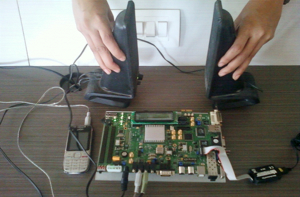
| The above mentioned problem is mainly due to the delay in the system, mainly in the feedback unit. We are trying to eliminate the delay by using the FPGA feedback circuitry. As being a fully hardwired system with embedded algorithm in same form. The system can make up to closest to the ideal format of the system. |
| The near field effect can be eliminated by using array of micro-phone and array of speakers. These can be arranged to get an optimum quite zone in the environment. The major complex system can be implemented on the microcontroller or micro-processor that can be interfaced with FPGA. |
B.3. USING FIELD PROGRAMMABLE LOGIC ARRAY (FPGA)
|
| Major problem in the system of implementation can be resolved by use of modes in the system. Most of the environmental can be simulated by this method. |
Features and Specifications
|
| • Packages supported PLCC84, TQ144 and PQ208. |
| • Upto 140 user I/Os. |
| • JTAG / Slave Serial. |
| • On board 8-MHz Clock oscillator (user selectable). |
| • Configurable 24 switches as I/P or O/P. |
| • Power on Reset and configuration reset key. |
| • 8-bit ADC/DAC add-on card. |
| • 16x2 character LCD display with contrast control. |
LEAKAGES AND COMBINATION NOISE REDUCTION (NR) AND ANC
|
| Some part of the noise may be lost in the capturing processing and the escaped noise may cause system unstable. The leakage signal is not processed in the hearing aid therefore it is not possible to improve its SNR using standard NR algorithms. It is possible however to attenuate the leakage signal’s noise component using ANC. In all the subsequent systems, it is assumed that a microphone is present in the ear canal to provide an error signal. Commercial hearing aids currently do not have an ear canal microphone, but it is technically possible to include a microphone on the ear tip. [12]the noise component which is leaked can compensate with noise reduction techniques. |
| It would be better if we could include the noise reduction and Active noise control together. It has the potential to bring out the best of the result in the futu/re. [12]A straightforward way to combine ANC and NR is to cascade both functional blocks, using the output of the noise canceller as the input to the ANC system. |
| In an ANC system, the controller output is designed to cancel a noise signal and generate a zone of quiet based on destructive interference. In a hearing aid, the noise is to be cancelled at the tympanic membrane and, as in any ANC system. The secondary path plays an important part in the algorithm. Introducing extra path may lead to instabilities. Therefore, it is necessary to use so-called filtered-x algorithms based on an estimate of the secondary path [9]. |
CONCLUSION
|
| In this paper we presented the techniques being used for the active noise control and their shortcomings. We also propose the more effective method of solving these shortcomings. The hard wired implementation can bring out vast change in the field of ANC and acoustics also. Several advantages of the FPGA can bring out very efficient result in the noise control. |
ACKNOWLEDGMENT
|
| We thank our teachers for their continuous support and encouragement in this work, for cultivating new and aspiring ideas in our mind. We would especially thank Prof. S. U. Bhandari for guiding through the process and being available for any problem faced. |
| |
Figures at a glance
|
 |
 |
 |
 |
| Figure 1 |
Figure 2 |
Figure 3 |
Figure 4 |
 |
 |
 |
 |
| Figure 5 |
Figure 6 |
Figure 7 |
Figure 8 |
|
| |
References
|
- P. A. Nelson, J. K. Hammond, P. Joseph, and S. J. Elliott, “Active control of stationary random sound fields,” J. Acoust. Soc. Amer., vol.87, p. 963, 1990.
- P. Joseph, S. J. Elliott, and P. A. Nelson, “Near field zones of quiet,” J.SoundVib, May 1994., vol. 172, no. 5, pp. 605–627.
- B. Rafealy, “Feedback control of sound”,Ph.d. Thesis,University of Southampton,UK,October 1997
- Paul Strauch, Member, IEEE, and Bernard Mulgrew, Member, IEEE “Active control of nonlinear noise processes in a linear duct” IEEE Transactions On Signal Processing, Vol. 46, No. 9, September 1998pp.2404,2410-2412.
- B. Rafaely, “Zones of quiet in a broadband diffuse sound field,” J.Acoust. Soc. Amer., vol. 110, p. 296, 2001.
- S.J.Elliot ,“signal processing for active control”,Academic press,2001.pp1-3
- AnkushGoel, AnoopVetteth, KoteRadhakrishnaRao, and Venkatanarayanan Sridhar “Active cancellation of acoustic noise using a self-tuned filter” IEEE Transactions On Circuits and Systems—I: Regular Papers, Vol. 51, No. 11, November 2004,pp. 2148-2149,2154-2156.
- Mika oinonen “Development of active noise control and voice communication system for personal hearing protectors ”Tempere university of technology ,22nd September,2006,pp4-5,18-26,44-54.
- RomainSerizel, Marc Moonen, Fellow, IEEE, Jan Wouters, and SørenHoldt Jensen, Senior Member, IEEE “Integrated active noise control and noise reduction in hearing aids” IEEE Transactions On Audio, Speech, And Language Processing, Vol. 18, No. 6, August 2010, Pg. 1-9.
- R. Serizel, M. Moonen, J.Wouters, and S. H. Jensen, “Integrated active noise control and noise reduction in hearing aids,” IEEE Trans. Audio,Speech, Lang. Proces, Aug. 2010., vol. 18, no. 6, pp. 1137–1146
- Cheng-Yuan Chang and Sheng-Ting Li-“Active noise control in headsets by using a low-cost microcontroller” IEEE Transactions On Industrial Electronics, Vol. 58, No. 5, May 2011pp. 1936-1940,1942.
- RomainSerizel, Marc Moonen, Fellow, IEEE, Jan Wouters, and SørenHoldt Jensen, Senior Member, IEEE “A zone-of-quiet based approach to integrated active noise control and noise reduction for speech enhancement in hearing aids” IEEE Transactions On Audio, Speech, And Language Processing, Vol. 20, No. 6, August 2012,pp.1685-1686,1695-1696.
- Woon S. Gan, Senior Member, IEEE, SohiniMitra and Sen M. Kuo Senior Member, IEEE-“Adaptive feedback active noise control headset: implementation, evaluation and its extensions”, Contributed Paper Manuscript received May 18, 2005 0098 3063/ © 2005 IEEE,pp.975-978,981.
- Michael Benoit, Christopher Camastra ,Melissa Kenny, Kimberly Li Richard ,Romanowski ,Kevin Shannon “Engineering Silence: Active Noise Cancellation”pp.1-12
- SonalNaik, MeenalPatil, ShrikantBhosale, Anjali Shrivastav “Verification unit for head light Parameters based on embeddedSystem” International Journal of Advanced Research in Electrical, Electronics and Instrumentation Engineering Vol. 2, Issue 1, January 2013
- Vipul B. Patel, Virendrasingh, Ravi H.Acharya “Design of FPGA-based All Digital PID Controller for Dynamic Systems” International Journal of Advanced Research in Electrical, Electronics and Instrumentation EngineeringVol. 1, Issue 2, August 2012
- DeepanRaj.B, T.V.P.Sundararajan, K.Shoukath Ali “ Fast Flexible FPGA-Tuned Networks-on-Chip” International Journal of Advanced Research in Electrical, Electronics and Instrumentation Engineering Vol. 2, Issue 1, January 2013.
|