Keywords
|
| Ultrasonic sensor, GPS module, GSM Modem, ARM 11 |
INTRODUCTION
|
| The vehicle accident is a major public problem in many countries, particularly in India. Despite awareness campaigns this problem is still increasing due to driver faults, inattention and low performance [1]. Increasing stress levels in drivers, along with their ability to multi task with infotainment systems cause the drivers to deviate their attention from the primary task of driving. Hence much emphasis is being given to occupant safety. |
| Although several research groups and major vehicle manufacturers have developed safety devices to protect drivers from accidental injuries. But it is difficult to implement good safety device for the vehicle using a single parameter [2]. Alternatively, intelligence schemes such as collision avoidance and location tracking have recently been devised to minimize the possibility of accident by using Ultrasonic system and GPS tracking system. |
| With the development of automotive industry, traffic load was increasing, and automotive safe driving issues were paid more and more attention [3], including collision avoidance control. Ultrasonic has good orientation and penetration, and has a certain ability to adapt to the environment. So, ultrasonic distance measurement system used in vehicle to avoid collision was feasible. |
| Ultrasound sensors are very versatile in distance measurement. They are also providing the cheapest solutions. Ultrasound waves are useful for both the air and underwater [1]. The main task of ultrasonic distance measurement is transmitting and receiving ultrasonic, and the processing of signal received by ultrasonic receiving circuit. |
| GPS module which is used for location tracking, communicated with 27 satellites to obtain geographic information. ARM 11 receives data from GPS module operated at refresh rate of 1Hz with UART interface. The data is decoded from GPRMC package using NMEA protocol, GPRMC or minimum recommended data consisting of basic GPS parameters including latitude (north or south), longitude (east or west), ground speed, current date and time, course over ground and magnetic variation. |
| A. The Principle of Ultrasonic Distance Measurement |
| Ultrasonic transducer uses the physical characteristics and various other effects of ultrasound of a specific frequency. It may transmit or receive the ultrasonic signal of a particular strength. These are available in piezoelectric or electromagnetic versions. The piezoelectric type is generally preferred due to its lower cost and simplicity to use [5]. |
| The Ultrasonic wave propagation velocity in the air is approximately 340 m/s at 15°C of air or atmospheric temperature, the same as sonic velocity. To be precise, the ultrasound velocity is governed by the medium and its temperature; hence the velocity of ultrasound in the air is taken as 343 m/s. Because the travel distance is very short, the travel time is little affected by temperature. It takes approximately 29.15μsec for the ultrasound to propagate waves through 1cm distance; therefore it is possible to have 1cm resolution in the system. |
| The sound waves with frequency higher than 20 kHz is called ultrasonic. In addition to the characteristics of sound waves (such as reflection, refraction and diffraction), ultrasonic has the characteristics of centralized direction, good penetration, and small amplitude [5, 7]. Therefore, ultrasonic has a great advantage on real-time, accuracy, non destructiveness, and so on. The ultrasonic which frequency is around 40 kHz has the best transmission efficiency. So, the frequency of the driver signal for the ultrasonic emitter used in this design is 40 kHz. |
| B. The Principle Of GPS Tracking System |
| The Global Positioning System (GPS) usually means a GPS receiver, the only fully-functional satellite navigation system. More than two dozen GPS satellites are in medium Earth orbit, transmitting signals allowing GPS receivers to determine the receiver's location, speed and direction [6]. |
| Each of these 3,000 to 4,000 pound solar-powered satellites circles the globe at about 12,000 miles (19,300 km), making two complete rotations every day. The orbits are arranged so that at anytime, anywhere on Earth, there are at least four satellites "visible" in the sky. Positioning System (GPS) is actually a constellation of 27 Earth-orbiting satellites (24 in operation and three extras in case one fails). |
| All satellites transmit on (1575.42 +/-10) MHz (L1) frequency, with C/A (Course/Acquisition coded 1023 kHz data and the system receiver works on this signal. The U.S. military developed and implemented this satellite network as a military navigation system, but soon opened it up to everybody else. A GPS receiver's job is to locate four or more of these satellites, figure out the distance to each, and use this information to deduce its own location. This operation is based on a simple mathematical principle called trilateration. |
| So the GPS receiver has to know two things: |
| - The location of at least three satellites above it |
| - The distance between the receiver and each of those satellites |
| The GPS receiver figures both of these things out by analyzing high-frequency, low-power radio signals from the GPS satellites. Better units have multiple receivers, so they can pick up signals from several satellites simultaneously. Radio waves being electromagnetic energy travel at the speed of light (about 186,000 miles per second, 300,000 km per second in a vacuum). The receiver can figure out the distance and time required for the signal to arrive. |
| Hence, Active safety system is the concept in which with the help of ultrasonic sensor, GPS module and ARM 11, possibility of accidents can be reduced [4]. |
SYSTEM IMPLEMENTATION
|
| A. Hardware- Ultrasonic Distance Measurement circuit |
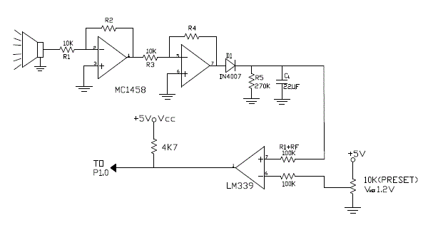
| In this paper, we describe such a measurement system which uses ultrasonic transmitter and receiver units mounted at a small distance between them. |
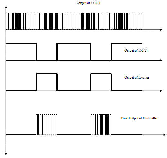
| Transmitter part contains two, 555 timer, AND gate (4081) and inverter IC (4049) 555(1) generates pulses with frequency 40KHz. Actually, ultrasonic transmitters are available with two frequencies 20KHz and 40KHz. 20KHz is typically not used as it fits within the voice band, it will be difficult to separate out voice noise from actual ultrasonic waves. Therefore the choice is 40 KHz. |
| Presently our target is to get waves from the other vehicle as well reflected waves. In that case, instead of continuous transmission of the waves, we will transmit it for very short duration; typically referred to as BURST signal. The burst of the signal will be transmitted for short duration. After that there will be silent period. The period is actually response time, i.e. waiting for reflected waves. If waves are reflected back, there is obstacle. To generate the burst we will require one for 555 IC with Less ON time and more OFF time. 555(1) generates 40 KHz signal. |
| Equation is 0.69 (Ra + 2 Rb) C |
| Select C - 0.01 μF |
| 1/ 40 KHz = 0.69 (Ra + 2 Rb) 0.01 X 10 E – [5] |
| This will give Ra = Rb = 1.1 K? [Approximately] |
| In 555 normally ON time is more and OFF time is less. Therefore we will invert the output of second 555 timer. 555(2) will generate such LOW frequency pulses. The speed of the ultrasonic wave is 330m/sec. |
| If we take range for reflected wave as 1m; the time required will be 1/330. It is equal to 3msec. For to-fro journey time required will be 6msec. |
| We will add some margin; i.e. 1.5 X 6msec = 9msec. Better to take it as 10msec. This time is response time once the wave is transmitted. Time to transmit the wave is 1/10 of 10msec, i.e. 1msec. |
| Finally we require ON time - 1 m sec and OFF time - 10 m sec. As mentioned 555 gives more ON time and less off time, therefore, |
| OFF time - 1 m sec and ON time - 10 m sec |
| 11msec = 0.69 (Ra + 2 Rb) C |
| Calculate the values taking C = 0.1μF |
| Finally, output of the 555(2) is inverted using 4049 IC. We have specifically selected CMOS IC so that we can operate at higher voltage levels i.e. 12V/15V.Output off 555(1) and Output of Inverter is AND together to get BURST signal. During ON time (1msec) we get 40 KHz pulses. For 10msec, we get LOW logic continuously. Within 1msec there will 40 pulses of 40 KHz frequency. |
| Now we are left with 5 inverters in the chip. Ultrasonic transducer operates on Piezoelectric principle [10] i.e. apply electrical signal and convert it to mechanical movement. In transducer, there is HORN kind structure that vibrates at 40 KHz frequency. The waves will be transmitted in air medium. The principle is fairly same as that of loud speaker. |
| To transmit the waves, we do transmit it with high power. Power means typically current quantity. Therefore inverters are used as buffer device (Boost the current). The final output of the inverter is fed to ultr5asonic transmitter. The waves will be now transmitted. |
| B. Software- GPS receiver Module |
| GPS receivers are used for navigation, positioning, time dissemination, and other research. Receiver displays real time data, which is speed and position. To store this data it is transferred to RAM of ARM 11[8]. It is then transferred to PC using RS 232 protocol [10]. |
| Here, HoluxGM-83 GPS module is used because of its high performance. It is the cheapest module in its class. Also it’s a compact module and having Independent operation board. It has direct communication interface with computer and it Supports NMEA0183 v2.2 data protocol [6,9]. |
| This GPS module having following specifications: |
| Receiver: 20 Channel, L1, Frequency, C/A Code, |
| Accuracy: 10m without SA; 100m with SA |
| Velocity: 0.6m/s |
| Acquisition time: Better than 60 seconds |
| Position update rate: Once per second |
| Input Power: 9 to 18V DC |
| Interface: 2 x RS 232C Port |
| Output: NMEA 0183 |
| This module has High speed signal acquisition using 1920 time / frequency search channels.It Built-in WAAS/EGNOS Demodulator.It has Low power consumption and Push-To-Fix mode.Also having an Optional Rechargeable battery for memory and RTC backup and for fast Time to First Fix (TTFF)[9]. |
| 1) Software Implementation: |
| This GPS allows 2 types of Programming i.e. Units Programming and NMEA Programming. We are using “NMEA Programming”. Example of sentence: |
| $GPGGA,1229.487,3723.2475,N,12158.3416,W,1,07,1.0,9.0,M,,,,0000*18: |
| The Unit outputs of the following messages are as shown below: |
| GGA- Global positioning system fixed data |
| GLL- Geographic position Latitude/Longitude |
| GSA- GNSS DOP and active satellites |
| GSV- GNSS satellites in view |
| RMC- Recommended minimum specific GNSS data |
| VTG- Course over ground and ground speed |
| The NMEA standard is proprietary and expensive. The settable parameters and options available for setting in NMEA Programming are as follows: |
| In the MAIN MENU screen of the GPS, choice ‘2’ is NMEA Programming, So the user presses numerical key 2. On selecting the choice 2 on the main menu, the NMEA Programming String is displayed as shown below: |
| a) The settable parameters and options available for setting in NMEA Programming are as follows: |
| b) On selecting the choice 2 on the main menu, the NMEA Programming String is displayed as shown below: |
| NMEA PROGRAMMING |
| NMEA: GPZDA |
| FREQUENCY: 0 |
| STATUS: ENABLE |
| REQUEST: ONCE |
| <ENT> to transmit <ESC> to return to the previous screen <UP ARROW> to scroll the options for item in the same field <DOWN ARROW> to move to the next field |
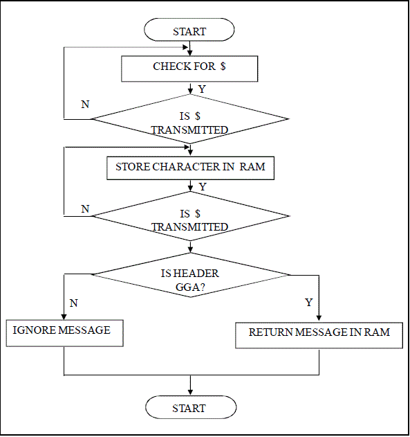
| The flow chart for Identification of GPS string is as shown in Fig.5. It is used for reading and analyzing the GPS receiver’s message. Here, data is uploaded from the GPS to the ARM 11, which receives data serially on its RxD pin. Since the data transmitted by GPS is in RS232 form, line driver MAX232 is used between the GPS and ARM to convert RS232 voltage levels to equivalent TTL levels. |
RESULTS
|
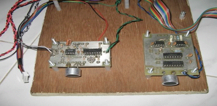
| The Experiments were done for the Hardware testing of Ultrasonic circuit and software implementation of GPS Module. The results of experiment for Ultrasonic circuit were seen on CRO and it gave the same output as shown in fig.7.Similarly, GPS module was tested and data transmitted from the GPS to the ARM 11 with the help of RS 232.ARM 11 received data serially on its RxD pin and display the same on LCD |
CONCLUSION
|
| This Active Safety System helps to prevent Accidents and to improve the performance of vehicle. ARM 11 is used because of its higher speed and to low cost. The device can be able to send GPS data and Ultrasonic circuit’s output periodically with high speed. The system can be tested in real world application using vehicles. In future, there is a scope to work on software implementation and testing of Ultrasonic circuit using ARM 11. |
| |
Tables at a glance
|
 |
 |
| Table 1 |
Table 2 |
|
| |
Figures at a glance
|
 |
 |
 |
 |
| Figure 1 |
Figure 2 |
Figure 3 |
Figure 4 |
 |
 |
 |
| Figure 5 |
Figure 6 |
Figure 7 |
|
| |
References
|
- AmardeepSathyanarayana, Pinar Boyrazs, ZelamPurohit, RosaritaLubag, John H.L.Hansen, J. H. L. Hansen,"Driver Adaptive & Context aware safety system using CAN Bus signals," 2010 IEEE Intelligent Vehicles Symposium,USA,June 21-24, 2010.
- Wassim G. Najm, Mark S. Mironer, Lynn C. Fraser “Analysis of Target Crashes and its Countermeasure Actions” America, 5th Annual Meeting, Washington, DC, March 15-17, 1995.
- National Highway Traffic Safety Administration official website (Online source, 2010, Feb)
- P. Boyraz, A. Sathyanarayana, J. H. L. Hansen, "In-Vehicle Multichannel Signal Processing and Analysis in UTDrive Project: Driver Behaviour Modeling and Active Safety Systems Development," 3rd International Conference ESAR, 5-6 September 2008, Hannover,Germany.
- Guohong Yan, XueboJin,"The Design of Ultrasonic distance Measurement System based on SOPC," 3rd International Conference on Intelligent Human Machine systems & Cybernetics, 5-6 September 2011, Hangzoue, China.
- GPS receiver, User’s Guide, 24th Sept.2002, published by Rekaline Marketing Corp., Taiwan.
- C. MacAdam,"Application of an optimal preview control for simulation of closed-loop automobile driving," IEEE Trans. Syst.Man. Cybrn., vol. SMC-11, pp.393-399, Sept 1981.
- http://www.friendlyarm.net/products/mini6410.
- T. Lomas, A. Tuantranont, "Wireless Black Box Using MEMS Accelerometer & GPS tracking for accidental monitoring of vehicles," Proceedings of the IEEE-EMBS International Conference on Biomedical & Health Informatics, 2-7 Jan 2012, Hong kong, China.
- Jing Yang, Student Member, IEEE, Edwin Hou, Senior Member, IEEE, and MengChu Zhou, Fellow, IEEE,” Front Sensor and GPS-Based Lateral Control of Automated Vehicles”, IEEE Transactions on Intelligent Transportation Systems, Vol. 14, No. 1, March 2013.
|