ISSN ONLINE(2319-8753)PRINT(2347-6710)
ISSN ONLINE(2319-8753)PRINT(2347-6710)
S.Nagakalyan1, Dr. B. Raghu kumar2, K.V.Abhilash3, Abhijeet Singh4
|
| Related article at Pubmed, Scholar Google |
Visit for more related articles at International Journal of Innovative Research in Science, Engineering and Technology
In this work, we are focusing on isolation of small members from heavy vibrations that is induced upon them due to surrounding members. Our major aim is to design a component, which is able to sense very small change in force, and is able to provide isolation to high accuracy. This isolation to be active in nature consists of electromotive force, which can be easily controlled and varied according to our need. To sense such precise and accurate vibration we are going to use a highly sensitive material that is PMNT PT coupled to an electronic circuit, which can generate equal response to vibration magnitude with equal frequency.
Keywords |
| Vibration, PMN PT, springs, Capacitance. |
I. INTRODUCTION |
| A number of environments commonly encountered possess mechanically harsh characteristics that can adversely affect some types of smaller devices attached with it. One example of this type of environment is vehicles, which can possess mechanical vibration characteristics ranging from 15 G with a 15 Hz bandwidth in 2.5 ton trucks to 50 G steady state 800 G transient with a 20 kHz bandwidth in small missiles. Another example is rotating machinery, which may range from balanced rotating shafts to severely unbalanced rotating members with impact loading. A final example is environments with high frequency audio noise, which includes some audio systems as well as mechanical systems designed to vibrate above the cutoff frequency of the human ear. Each of these environments possesses large amplitude mechanical motion in the higher end of the audio frequency range. Some smaller devices are particularly sensitive to this environment. Examples include resonating MEMS gyroscopic sensors, some micro-optic components, and some high frequency oscillators such as surface transverse wave (STW) resonators. The result can range from increased noise floor to catastrophic failure. Some micro-optic based systems require that distances between microoptical surfaces be precisely maintained. If environmental vibrations propagate into the micro-optic system and change the relative distances between the optical surfaces, the system may cease to operate correctly. Mechanical shock loading can affect a broader range of devices and other micro devices, resulting in physical damage to the microstructures themselves from exposure to high accelerations. |
| The first choice for mitigating this dilemma is usually to exclude vibration sensitive components from applications in mechanically harsh environments, as long as other components exist that will allow the system to function adequately. If that is not possible, a second choice is to integrate a macro vibration isolation platform into the system to protect large portions of the system from the environment. However, both choices usually come with penalties such as increased cost, size, weight and power usage, and possibly decreased performance. Recently though, component level vibration isolation approaches have been investigated to isolate an individual sensitive component from exposure to environmental vibrations. Since many of the sensitive devices are primarily sensitive to high frequency vibration components present in the operating environment, and may even require undistorted access to low frequency components, an active vibration isolation filter can potentially be utilized as a vibration isolation platform for the sensitive device. |
II. CONCEPT |
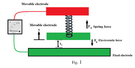
| Consider the simple parallel plate capacitor illustrated in Fig. 1, where each electrode has an overlapping area, A, the voltage across the two electrodes is V, and a rest separation distance, xo, exists between the electrodes when V= 0 V. Let I (t) be defined as the current flowing into the capacitor. |
 |
| For operation as a parallel plate electrostatic actuator, a large voltage is applied across the two electrodes, which produces an electrostatic force, Fe, which attempts to pull the two electrodes into contact along the x-axis. A first order model for Fe is |
| Fe = (εoεrΑν2 ⁄ 2(x+x0)) |
| Where εoεr is the permittivity of the dielectric material between the two parallel electrodes, A is the overlapping electrode area, V is the voltage applied across the two electrodes, and xo+x is the electrode separation distance. When the applied voltage is 0 V, the two electrodes are separated by the rest distance, xo. As is increased from zero, the movable electrode moves toward the fixed electrode until the spring force equals the electrostatic force. The force balance equation is |
| kx = (εoεrΑν2 ⁄ 2(x+x0)) |
| Where k is the system spring constant. For a nonzero small value of V, two solutions exist for x, one stable and one unstable. The stable value for x is always less than 1/3 of xo. As V is increased, the two solutions for x move closer together, and finally converge to the same value, 1/3 of xo. The voltage where this occurs is called the pull-in voltage, Vpo. For any voltage equal to or greater than Vpo, the movable electrode will snap in or “pull in” to contact with the fixed electrode. Therefore, the stable operating range of the parallel plate actuator |
| 0 < x < 0.333xo |
III SENSING ELEMENT |
| The material used to sense the vibration is PMN PT. The properties of the material are: - CE MATRIX [elasticity matrix]{11.5E10, 10.5E10, 11.5E10, 11.44E10, 11.44E10, 12.6E10, 0, 0, 0, 6.3E10, 0, 0, 0, 0, 6.3E10, 0, 0, 0, 0, 0, 6.5E10} Pascal’s e matrix {coupling matrix}{0, 0, -4.69, 0, 0, -4.69, 0, 0, 25.6, 0, 0, 0, 0, 0, 0, 0, 0, 0} C/m2; Permittivity 2687; Density 8100 kg/m3; Poisson’s ratio 0.37;Young’s modulus 72e9 Pascal. |
| Using COMSOL software we have calculated the value of potential difference generated due to application of cyclic load. The result is tabulated as below |
 |
| Deflection observed in the material was 3.9038 micrometers at Eigen frequency was 9472.561 Hz. Due to this deflection a electric potential of 8mv was generated. Hence the sensitivity of the device is increased tremendously. |
IV. WORKING |
 |
| Now we know that vibration is cyclic in nature, which changes its magnitude and direction with time. So to isolate a component from vibration we need to provide a force of same magnitude but in opposite sense such that from principle of equilibrium of forces vibration gets canceled. |
 |
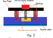
| Let us assume that the vibration is of positive magnitude and trying to push the bottom plate upwards but there is piezoelectric material PMNT PT, which is attached to the top plate using a center spring. So while moving up, the spring exerts a force the piezoelectric material generates which causes a strain in the piezoelectric material and due to this a corresponding voltage. Hence we can conclude that voltage generated in material is a function of force acting on the plate and this voltage is sent to the control unit. Thus using this we can find the magnitude of force which has to be applied in other direction to cancel the force. |
| This is done by varying the voltage across the plates, as the voltage is increased the plate pushes it down and a downward force exerts which cancels the vibration as well as compresses the spring in the process. When a reverse force acts on the bottom plate the voltage between the plates is reduced so that the energy stored in the spring is used to push the plate upward. Hence the opposite force cancels each other |
V. CONCLUSION |
| Though theoretically vibration can be cancelled but in actual practice the vibrations cannot be eliminated completely. The level of reduction in vibration will depend on the accuracy and precision in measuring the force and generating the opposing force. Hence the components that were induced to heavy vibration will now be subjected very light vibrations and the cost of constructing very robust components will also be reduced. |
References |
|