An efficient implementation of tool identification system based on feature extraction technique is proposed and validated. Principal Component Analysis (PCA) is used for extracting features from a large training database images of different classes of tools like spanner screwdriver, knife and hammer. Original image from each class is rotated by 5° to obtain 72 training images for each individual class of tools. In the proposed method, the initial computation of features of the training images using PCA is computed for the entire database and is saved in the memory. Computed results are loaded from memory when a test image is provided to the system for identification. Simulation results shows that proposed method can recognize a tool within 15 seconds from the database containing 288 training images and hence the proposed method can be used for real time tool identification systems.
Keywords |
| Principal component analysis; eigen values; eigenvectors; covariance matrix. |
INTRODUCTION |
| Object recognition systems [1] are employed in many applications, such as industry and assembly lines, robotics,
object grouping, object tracking, face recognition etc. All of these applications require a computer vision program able to
recognize different types of objects. The recognition of objects in an assembly line or objects travelling on a conveyor
belt requires that the training database and all relevant information for recognition be previously stored in the machine
memory and loaded when required in order to ensure fastest response . Machines, unlike humans need the translation of
pictures into a machine understandable format. This is achieved by extracting features from images, and then the features
are used to classify and recognize objects. This is done by comparing these features with previously stored database of
known features of different objects. |
| Principal Component Analysis (PCA) [2] is one of the most successful techniques that have been used in image
recognition, feature extraction and compression. PCA is a statistical method under the broad title of factor analysis. The
purpose of PCA is to reduce the large dimensionality of the data space (observed variables) to the smaller intrinsic
dimensionality of feature space (independent variables), which are needed to describe the data economically. This is the
case when there is a strong correlation between observed variables. The jobs which PCA can do are prediction,
redundancy removal, feature extraction, data compression, etc.
Rest of the paper is organized as follows. Section II deals with PCA and its mathematical background. Proposed
method and simulation results are discussed in section III. Section IV compares three different implementation methods
of the proposed tool identification system and finally section V concludes the paper. |
PRINCIPAL COMPONENT ANALYSIS |
| Much of the work in automatic object detection has focused on extracting the dimensional properties of the object to
be recognized. The use of edges, control points etc to measure lengths, angles etc lead to complex and time consuming
techniques of pattern recognition. The relevant information in the image of an object is to be extracted, encode it as
efficiently as possible, and compare one object encoding with a database of models encoded similarly. Capture the
variation in a collection of images and use this information to encode and compare the objects. In mathematical terms,
find the principal components of the distribution of the objects (tools in this case), or the eigenvectors of the covariance
matrix of the set of tool images, treating an image as a point (or a vector) in a very high dimensional space. The
eigenvectors are ordered, each one accounting for a different amount of the variation among the images of the tools.
These eigenvectors can be thought of as a set of features that together characterize the variation between the images of
tools. Each image location contributes more or less to each eigenvector so that an eigen image can be compiled. Each
individual image in the database can be represented exactly in terms of a linear combination of the eigen images. In
principle any collection of images of the tools [3] can be approximately reconstructed by storing a small collection of
weights for each object. The weights describing each image of a tool are found by projecting the face image onto the
eigen image. |
| This approach to object recognition involves the following initialization operations: |
| 1. Acquire an initial set of training images |
| 2. Calculate the eigen images from the training set, keeping only the M images that correspond to the highest
eigen values. These M images define the image space. |
| 3. Calculate the corresponding distribution in M-dimensional weight space for each known object, by
projecting its image onto the image space. |
| Having initialized the system, the following steps then used to recognize new test images: |
| 1. Calculate a set of weights by projecting the input image onto each of the eigen images. |
| 2. Determine if the image is a known object at all, by checking to see if the image is sufficiently close to
image space. |
| 3. If it is an object, classify the weight pattern as either a known object or as unknown. |
| A. Mathematics behind PCA |
| A 2-D image can be represented as 1-D vector by concatenating each row (or column) into a long thin vector.
Consider M vectors of size N ( rows of image × columns of image) representing a set of sampled images. pj s represent
the pixel values. |
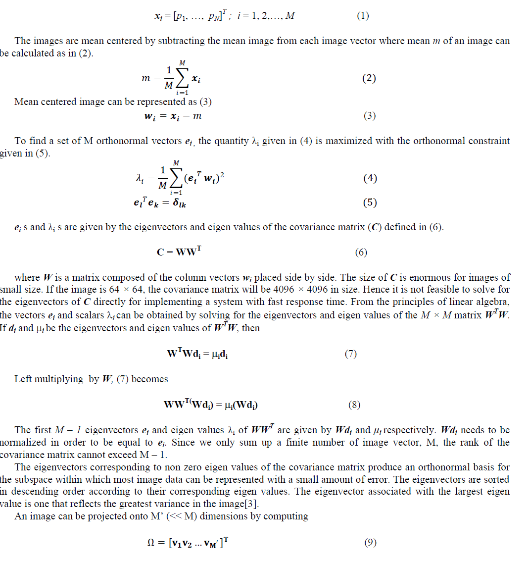 |
| where vi = ei
T wi. vi is the ith coordinate of the image in the new space, which is the principal component thus
obtained. The vectors ei are called eigen images. So Ω describes the contribution of each eigen image in representing the
object image by treating the eigen images as a basis set for object images. The simplest method for determining which
object class provides the best description of an input test image is to find the object class k that minimizes the Euclidean
distance (εk) given in (10). |
 |
| where Ωk is a vector describing the kth object class. If εk is less than some predefined threshold θc , an object is
classified as belonging to the class k. |
PROPOSED METHOD: IMPLEMENTATION AND RESULTS |
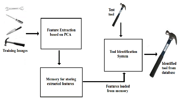
| The block diagram of the proposed method is shown in Fig. 1. Features are extracted and stored in the memory and
loaded for identifying a feature when a test tool is provided. For the implementation of the tool identification system,
tools belonging to 4 different classes namely spanner screwdriver, knife and hammer. 72 rotated samples of each
class made up the training database, making a total of 288 training images. Each training image in a class differs from
its adjacent samples by a rotation angle of 50. |
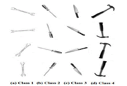
| Sample images from the training database for the four different classes of tools are shown in Fig. 2. To create a set
of images for testing, the original non rotated sample from each class is rotated [4] 72 times, each time by 5°. Test
samples for each class were chosen randomly from these rotated images. |
| The database was loaded on to the computational software, MATLAB in this case, and all the required features were
extracted. The features used for the recognition of the class or tool are the weights of projection of the images [5],[6] on
to the eigen image space. These features were calculated for the existing training database and stored for use in
recognition. The number of eigen images required to perform accurate recognition is much lesser than the number of
training images. From 288 images that were included in the training database, only 146 eigen images were required to
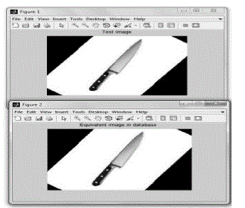
accurately identify the equivalent of the test image in the training database. Simulation results of the proposed method
indicating true identification of test image from database is shown in Fig. 3. |
COMPARISON OF TOOL IDENTIFICATION TIME |
| Object identification time of the proposed method (Method II and Method III) is compared with the existing method
(Method I). Method I performs all the computations including, database creation, PCA feature extraction and object
recognition for a test image. The existing method requires more computation time and hence it is less efficient. Method
II saves the entire database in a memory and loads the database from the memory when a test image is applied to the
system for identification thereby reducing execution time. All the initial computations including database creation and
PCA feature extraction are saved in a memory location in Method III making proposed system more efficient and
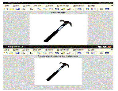
suitable for real time applications. Fig. 4 shows the simulation results for tool identification where first one is the test
image and second one is the identified tool from the database.. |
| The initial computation of features of the training images is the most time consuming part of the system. Once these
computations are saved, they have to be updated only when new training images are encountered. For recognition,
these features are simply loaded from memory. The time required to identify a tool after navigating through the
projections of 288 training images only comes to about 15 seconds. Thus the proposed system serves as quite an
efficient system for recognizing the objects in the image. If only the database is saved according to Method II, the
program execution time is about 55 seconds. If the database is computed every time the test image is given as per
Method I, the program execution takes about 5 minutes as shown in Table I. Instead of using a threshold value to
determine the class of a test image, Euclidean distance between weights of projection of the eigen image to the
projection of the test image is used. |
| To improve the accuracy of the system in practical applications, the training database can be expanded to include
other variations that may be present in the image, in terms of skew, position etc. Imposing a threshold will also improve
the accuracy of the system. This will enable the test object to be rejected on ground of not being close enough to any of
the training images. A neural network implemented to perform the same task with the same accuracy will be overly
complex and will take a large time to train. This is particularly disadvantageous in case of an expanding training database.
Also the extraction of features that could effectively characterize these images will also prove difficult. One of the
simplest methods require determining the outermost edges of the object in the image. The centroid of the object is
calculated and the distance of the edges from this point at different angles can be combined to a feature vector. These
vectors for different images can be mapped to respective targets based on their classes. This approach does not guarantee
the accuracy that PCA does. |
CONCLUSION |
| An efficient tool identification system using Principal Component Analysis is proposed and validated. Simulation
results shows that the proposed method is most effective and accurate approach to identify and classify tools. Proposed
method takes only 15 seconds to identify a tool from the database. This has been more apparent after an attempt to use a
traditional neural network for achieving the same task. The same technique can be adapted into object recognition
systems of differing capacities depending on the functionality required. |
Tables at a glance |
 |
| Table 1 |
|
| |
Figures at a glance |
 |
 |
 |
 |
| Figure 1 |
Figure 2 |
Figure 3 |
Figure 4 |
|
| |
References |
- Aljarrah, I. A., Ghorab, A. S., and Khater, I. M., âÃâ¬ÃÅObject Recognition System using Template Matching Based on Signature and PrincipalComponent Analysis, âÃâ¬Ã International Journal of Digital Information and Wireless Communications, Vol. 2, no. 2, pp. 156âÃâ¬Ãâ163, 2012.
- Diamarantas, K. I., and Kung, S. Y., âÃâ¬ÃÅPrincipal Component Neural Networks: Theory and Applications,âÃâ¬Ã John Wiley & Sons, Inc., 1996.
- Turk, M. and Pentland, A., âÃâ¬ÃÅEigenfaces for Recognition,âÃâ¬Ã Journal of Cognitive Neuroscience, Vol. 3, no. 1, 1991.
- Jain, A. K., âÃâ¬ÃÅFundamentals of Digital Signal Processing,âÃâ¬Ã Prentice Hall of India Pvt. Ltd., 2005.
- Gonzalez, R. C., and Woods, R. E., âÃâ¬ÃÅDigital Image processingâÃâ¬ÃÂ, second edition, Pearson Education inc. 2002
- Gonzalez, R. C., Woods, R. E., and Eddins, S. L., âÃâ¬ÃÅDigital Image processing using MATLAB,âÃâ¬Ã Pearson Prentice Hall, 2003.
|