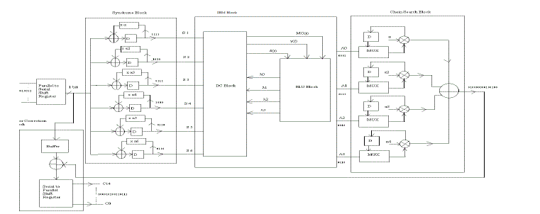
Error-correction codes are the codes used to correct the errors occurred during the transmission of the data in the unreliable communication mediums. The idea behind these codes is to add redundancy bits to the data being transmitted so that even if some errors occur due to noise in the channel, the data can be correctly received at the destination end. Bose, Ray- Chaudhuri, Hocquenghem (BCH)codes are one of the error-correcting codes. The BCH decoder consists of four blocks namely syndrome block, IBM block, chien search block and error correction block. This paper describes a new method for error detection in syndrome and chien search block of BCH decoder. The proposed syndrome block is used to reduce the number of computation by calculating the even number syndromes from the corresponding odd number syndromes. The new factorization method used to implement the algorithm of chien search block of enhanced BCH decoder reduces the number of components required. Thus, a new model of BCH decoder is proposed to reduce the area and simplify the computational scheduling of both syndrome and chien search blocks without parallelism leading to high throughput. The enhanced chase BCH decoder is designed using hardware description language called Verilog and synthesized in Xilinx ISE 14.3.
Keywords |
| BCH Codes, Syndrome Block, Chien search Block, Error detection |
INTRODUCTION |
| The information theory and coding theory are used in computer communication and telecommunication applications.
Error correction and detection are the techniques used in the above mentioned applications that enable reliable delivery
of digital data over unreliable communication channels. Many communication channels are subjected to channel noise
which introduces the errors during transmission of messages from the source to receiver [1][6]. The channel coding
theory states that the reliable transmission is achievable by performing proper coding. “Channel Coding” is the
technique, which is used to sustain the originality of the information bits, to avoid the retransmission of information
bits as well as to detect and correct any error which has been occurred during transmission. |
| Error detection is the detection of errors caused by noise or other impairments during transmission from the transmitter
to the receiver.It uses the concept of redundancy[8], which means adding of extra bits for detectingerrors at the
destination. In error correction the receiver can use any of the error-correcting code, which can automatically corrects
certain errors and enables reconstruction of the original data. |
| A. Detection Methods |
| 1) Repetition codes: |
| A repetition code is coding scheme that repeats the bit across a channel to achieve error-free communication.
Repetition codes are very inefficient and can be susceptible to problems if the error occurs in exactly the same place for
each group. |
| 2) Cyclic Redundancy Checks (CRC): |
| A CRC is a single-burst error –detecting cyclic code designed to detect accidental changes to design to detect
accidental changes to digital data in computer networks. It is not preferable for detecting maliciously introduced errors. |
| 3) Parity Bit: |
| These are the simplest form of error-detecting code. They can detect single or any other odd number of errors in the
output. Even parity is a special case of a cyclic redundancy check (CRC), where the 1-bit CRC is generated by the
polynomial x+1. |
| B Correction Methods |
| 1) Automatic Repeat Request (ARQ): |
| Automatic Repeat request (ARQ) is an error control method for data transmission that makes use of error-detection
codes, acknowledgment and negative acknowledgment messages and timeouts to achieve reliable data transmission.
ARQ is appropriate if the communication channel has varying or unknown capacity. It requires the availability of a
channel, results in possibly increased latency due to retransmissions and requires the maintenance of buffers and timers
for retransmissions. |
| 2) Forward Error Correction (FEC): |
| An error-correcting code (ECC) or forward error correction (FEC) code is a system of adding redundant data or parity
data, to a message, so that the message can be recovered by a receiver even when a number of errors are introduced,
during the process of transmission.Aback-channel is not required in forward error correction since the receiver does not
have to ask the sender for retransmission of the data [9]
[10]. |
| Error-Correcting codes are futureclassified into two major class of codes such as convolutional codes and block codes:
Convolutional codes: |
| They are processed on a bit-by-bit basis. They are suitable for implementation in hardware and many algorithms exist
for decoding these codes. The Viterbi algorithm provides high performance.Thus the Viterbi decoder is commonly used
which allows optimal decoding. |
| Block Codes: |
| The block codes are implemented as (n, k) codes where n indicates the codeword and the k defines the original
information bits. Therefore, the numbers of redundant bits need to be added in to the original message bits are given as
(n-k) the block codes are fixed channel codes.BCH codes are subset of the Block codes. |
| The objective of this work is to reduce the number of components used in both in syndrome and chien search blocks[5]
[3].The new factorization method which allowed to conceive another chien search block with reduced number of logic
gates. |
| This paper is organized as follows; Section II BCHencoder_lfsr design and architure IIIexplains the modifiedBCH
decoder and detailed structure of syndrome and Chiensearch respectively. Section IV shows the simulation resultsof the
enhanced BCH (15,5) and Results are analyzed.Section V is drawn with the conclusion. |
ENCODER_LFSR DESIGN ANDARCHITECTURE FOR BCH CODE |
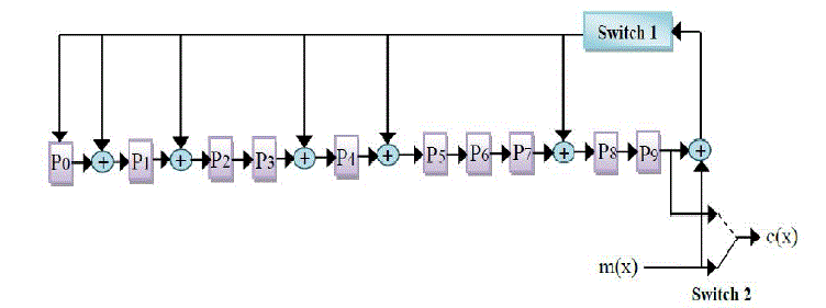
| The Encoder_LFSR design used in this project is most commonly used in the modern digital communication system.
This encoder_LFSR design is almost common to all the BCH code architecture, which uses the linear feedback shift
register for polynomial division. |
| The format of the codeword is as follows [4]: |
| c(x) = xn-k * i(x) + b(x) (3.1) |
| Where, codeword c(x) = c0 + c1x +...+ cn-1xn-1 |
| information bits i(x)= i0 + i1x +...+ ik-1xk-1 |
| remainder b(x)= b0 + b1x +...+ bm-1xm-1 |
| also, ci, ji, bi are the subsets of Galois field. If b(x) is taken to be the polynomial such that the k data bits will be
presented in the codeword, which is given as follows: |
| xn-k * i(x) = q(x) * g(x) - b(x) (3.2) |
| BCH codes are implemented as cyclic code. As a result the logic which implements encoder_LFSR and decoder is
controlled into shift register circuits. With the help of cyclic code properties the remainder b(x) can be calculated in the
linear (n-k) stage shift register with the feedback connection to the coefficient of generator polynomial. |
| The original message bits are transmitted without changing its form (during this operation switch s2_in is in position
2), and the linear [2] The generated parity bits in the linear feedback shift register are transmitted (switch s2_in is inFor
cycle k+1 to n, position 1) and the feedback in the LFSR is switch off (s1_in off). feedback shift register calculates the
parity bits (switch s1_in is on now). |
DECODER DESIGN AND ARCHITECTURE FOR BCH CODE |
| The BCH decoder has four modules as mentioned below: |
| - Syndrome Calculator |
| - Solving the key equation |
| - Error Location |
| - Error Correction |
| The implementation and the algorithms used to design above modules are varies with the architectures. The 2nd
module, Solving the key equation is the most difficult and complex module as compared to the other modules in respect
to the hardware complexity. This chapter contains the detailed explanation of the different algorithms used to
implements those modules. |
| 1. Syndrome Calculator:The syndrome calculator is the first module at the decoder also, the design of this module is
almost same for all the BCH code decoder architecture. The input to this module is corrupted codeword. The equations
for the codeword, received bits and the error bits are given in equations (5.1), (5.2), (5.3)[4]. |
| Codeword equation |
| c(x) = c0 + c1x + c2x2 + ... + cn-1xn-1 (5.1) |
| Received bits equation |
| r(x) = r0 + r1x + r2x2 + ... + rn-1xn-1 (5.2) |
| Error bits equation |
| e(x) = e0 + e1x + e2x2 + ... + en-1xn-1 (5.3) |
| Thus, the final transmitted data polynomial equation is given as below: |
| r(x) = c(x) + e(x) (5.4) |
2. Key Equation Solver: The second stage in the decoding process is to find the co-efficient of the error location
polynomial using the generated syndromes in the previous stage. The error location polynomial is given as:   The relation between the syndromes and the error location polynomial is given as below [4]: The relation between the syndromes and the error location polynomial is given as below [4]: |
 |
| There are various algorithms used to solve the key equation solver. This project is using the Inversion less Berlekamp
Massey algorithm to solve the key equation. |
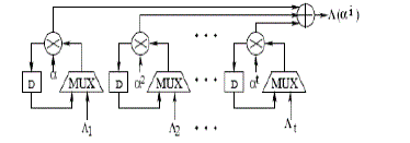
| 3. Error Location – Chain’s Search: To calculate the error location is the next step of decoding process, which can be
done using chain search block. |
| 3.1 Chain Search Algorithm |
| The roots are calculated as follows [12] [4]: |
| 1. For each power of α for ( j = 0 to n – 1), αj is taken as the test root |
| 2. Calculate the polynomial coefficients, of the current root using, coefficients of the past iteration, using, Λ i
(j) = Λ i
(j-
1) αiduring the jth iteration |
| 3. Calculate the sum of the polynomial coefficients |
 |
| 4. The sum is equal to |
| 5. Continue to Step 1 till j = n-1 |
| Error Correction Block output: |
| Codeword = r(x) ^ e(x) = ‘000010100110111’ |
| So, the codeword is generated by adding the message bits with parity bits and transmitted over to the decoder. The data
get corrupted during the transmission. The decoder will decode the corrupted data and retrieve the original codeword. |
| 4. Error Correction: The output of the chain search block is called roots of equation. The reciprocal of the roots of
equations are added with the corresponding location of the corrupted codeword received by decoder. The result of this
addition is the original codeword that was encoded by the encoder before transmission. |
SIMULATION RESULTS |
Block diagram |
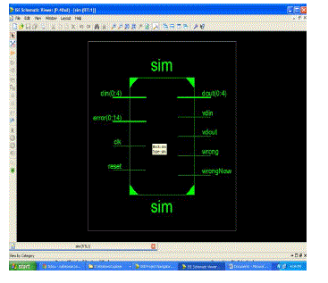 |
RTL schematic |
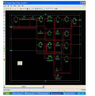 |
Technology schematic |
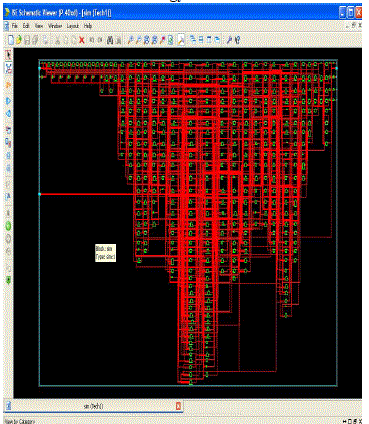 |
| Design summary |
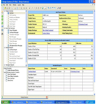 |
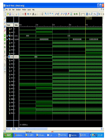
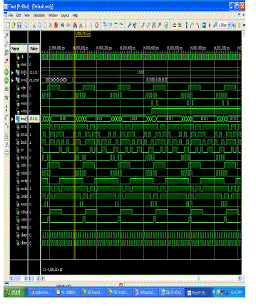
Simulation output wave forms |
 |
 |
CONCLUSION |
| This project covers the detailed explanation about the necessity of Error correcting code along with the comparison of
various error correcting codes and high speed (15, 5) BCH code Encode and Decoder design. The previous chapters
discuss the design technique of encoder and decoder, and the behavior of the designs are described using Verilog. The
simulation of the code is done in Xilinx Modelsim. Also, the encoder and decoder design is synthesized in Xilinx ISC
14.3 wabepack to generate the gate level netlist. The design steps, input signals and output signals along with the
simulation results of design and synthesis result are discussed in detail in pervious chapters. |
| |
Figures at a glance |
 |
 |
 |
 |
| Figure 1 |
Figure 2 |
Figure 3 |
Figure 4 |
|
| |
References |
- R.C. Bose, D.K. Ray-Chaudhuri, âÃâ¬ÃÅOn a class of error correcting binary group codesâÃâ¬ÃÂ, Inf. Cntrl, 3, pp. 68-79, March 1960.
- H.O. Burton, âÃâ¬ÃÅInversionless decoding of binary BCH codeâÃâ¬ÃÂ, IEEE Trans., 1971, IT- 17, (4), pp. 464-466.
- C. E. Shannon, ``A mathematical theory of communication,'' Bell System Technical Journal, vol. 27, pp. 379-423 and 623-656, July and October, 1948.
- Ernest Jamro, âÃâ¬ÃÅThe Design of a VHDL based synthesis tool for BCH codesâÃâ¬ÃÂ, The university of Huddersfiel, September 1997.
- W.W. Peterson, E.J. Weldon, âÃâ¬ÃÅError correcting codesâÃâ¬ÃÂ, MIT Press, Cambridge, MA, 1972.
- W.W. Peterson, âÃâ¬ÃÅEncoding and error-correction procedures for the Bose-Chaudhuri CodesâÃâ¬ÃÂ, IRE Trans. Inf. Theory, IT-6, pp. 459-470,September 1960.
- Joel Sylvester âÃâ¬ÃÅReed Solomon CodesâÃâ¬ÃÂ, Elekrobit., January 2001.
- G. D. Farney, lr., "The Viterbi algorithm", Proc. IEEE, vol. 61, pp. 268-278, Mar. 1973.
- Softjin technology, âÃâ¬ÃÅData sheet for BCH encoder_LFSR coreâÃâ¬Ãâ¢, India, Dec 2000, www.softjin.com.
- Hanho Lee, âÃâ¬ÃÅAn area-efficient Euclidean Algorithm block for Reed-Solomon DecoderâÃâ¬ÃÂ, Dept. of ECE, University of Conecticut, Srorrs, CT06269, USA.
- Dilip V. Sarwate, Naresh R. Shanbhag, âÃâ¬ÃÅHigh-Speed Architectures for Reed-Solomon Decoders,âÃâ¬Ã IEEE Trans.On VLSI Systems, vol.9 No.5, Oct. 2001.
- Yanni Chen, Keshab K. Parhi, âÃâ¬ÃÅArea Efficient Parallel Decoder Architecture for Long BCH CodesâÃâ¬ÃÂ, Dept. of ECE, University of Minneapolis, MN 55455 USA
- Clifford Kraft, âÃâ¬ÃÅClosed Solution of BerlekampâÃâ¬Ãâ¢s Algorithm for Fast Decoding of BCH CodesâÃâ¬ÃÂ, IEEE Transactions on Communications, Vol. 39, No. 12, December1991.
|