Direct Torque Control (DTC) of induction motor drives has become very popular and widely used in industrial applications due to its fast and good dynamic torque response. Induction motors(IM) are simple in construction and are less sensitive to the motor parameters compared to other vector control methods. The conventional DTC is based on flux and torque hysteresis controllers. Induction motor is fed from a Four Switch Three Phase Inverter (FSTPI) generating the voltage vectors of the Six Switch Three Phase Inverter (SSTPI) by emulation. Applying the most optimized voltage vector that produce the largest tangential component to the circular flux locus can accomplish the fastest dynamic torque response during transient states. The dynamic torque performance is very important in traction and electric vehicle application. A method to achieve fastest dynamic performance by modifying the two leg inverter fed DTC of induction motor based on Fuzzy Logic Concept (FLC) is discussed in this paper. FLC is one of the Artificial Intelligence methods have found high application in most of the nonlinear systems like the electric motor drives. FLC can be used as controller for any system without requirements of the system mathematical model unlike that of the conventional electric drive control, which uses the mathematical model. This paper presents a rule-based fuzzy logic controller scheme designed and applied for the speed control of an induction motor fed from a four switch three phase inverter emulating the six switch three phase inverter. Due to the usage of the FLC concept, the efficiency, reliability and performance of ac drive increases. Initial torque peak and torque ripple are minimized in the four switch three phase inverter based DTC using Fuzzy Logic.
Keywords |
| Direct Torque Control(DTC), Four/Six Switch Three Phase Inverter (FSTPI/SSTPI), Fuzzy Logic
Concept(FLC), Induction motor(IM), Emulation, Voltage Vectors |
INTRODUCTION |
| DC motors were used extensively for variable speed drives applications in past decades due to advantage that their flux
and torque could be independently controlled by the field and armature current.Absence of mechanical commutator and
brush assembly, rugged construction, simple structure and less maintenance requirement are makes AC induction motor
are more acceptable than DC motors. In normal reference frames, the torque and flux of an induction motor are coupled
together and hence independent control becomes difficult. Rapid advancement in high-power semiconductor devices
and high speed digital signal processing has enables decoupling of torque and flux giving rise to high performance
induction motor drives capable for variable-speed performance. Now a day’s induction motors are the work horse of
the industry. The two important control methods of induction machines can be classified into scalar and vector control.
Both Vector Control and Scalar control aim to control effectively the motor torque and flux in order to force the motor
to accurately track the command trajectory regardless of machine and load parameter variations. In scalar control, the
magnitude and frequency of voltage is controlled, where as in vector control, the instantaneous position as well as the
magnitude and frequency of voltage, current and flux linkage space vectors are controlled.Field Oriented Control
(FOC) and Direct Torque Control (DTC) are the two most popular methods of vector control for high performance AC
drives. Compared to FOC, DTC can provide extremely high dynamic response with very simple structure. The first
DTC strategy involves a simple control scheme which makes it possible rapid real time implementation as in [1]. The
variable switching frequency and the ripples in flux and torque are the main drawbacks of conventional DTC. Hence
several investigations are carried out in areas of high torque ripple and uncontrolled switching frequency which results
development of several DTC strategies have been proposed so far as in [3]-[4]. One of them is considering variable hysteresis band controllers as in [5]. Reconfiguration of SSTPI into a four-switch three inverter(FSTPI), in case of a
switch/leg failure can be done where reliability is more important as in [6]-[7]. This paper proposes a new FLC based
DTC strategy dedicated to FSTPI-fed IM drives. Fuzzy logic improves the performance of the FSTPI-fed DTC strategy
of induction motor. It is based on the emulation of the SSTPI operation and the synthesis of an appropriate vector
selection table, which is based on the hysteresis controllers and flux vector position as in [2] |
FUZZY LOGIC BASED DTC OF FSTPI-FED INDUCTION MOTOR DRIVES |
| Direct Torque Control is a control technique used in AC drive system to obtain high performance torque control by
which it is possible to control directly the stator flux and the torque by selecting the appropriate inverter switching
state. Since its introduction, DTC based induction motors are being increasingly used in various industrial applications.
The Direct torque control method is characterized by its simple implementation and a fast dynamic response. |
| A. Basic DTC |
| The conventional DTC drive using hysteresis comparators as two level flux controller and three level torque controller
and their outputs are flux error and torque error respectively. It consists of flux and torque estimator, six switch three
phase inverter and a voltage vector selection table.The SSTPI can generate eight balanced voltage vectors.Eight
voltage vectors consists of six active voltage vectors and two zero voltage vectors. The active voltage vectors have the
same magnitude and are phase shifted each by an angle of 60°. Direct Torque Control allow a direct control of the
motor variables through an appropriate selection of the inverter control signals, in order to fulfill the requirements as
whether the stator flux and torque need to be increased, decreased or maintained.These decisions are achieved
according to the output C φ of the flux hysteresis controller, the output C τof the torque hysteresis controller, and the
angular displacement θ s of the stator flux vector φ s in the Clarke ( α β ) plane. The torque and flux are controlled
simultaneously by applying suitable voltage vectors of the eight balanced voltage vectors of the SSTPI. |
| B. FSTPI-fed DTC Strategy |
| The implementation scheme of the DTC strategy dedicated to the FSTPI-fed IM has the same layout as the one of the
basic DTC strategy except that the SSTPI inverter is reconfigured to a FSTPI by removing one leg of the 3 leg inverter
and the three level hysteresis controller in the torque loop is replaced by a two level hysteresis controller. This
replacement is done because of the fact that no zero voltage vector is involved in the new DTC scheme. |
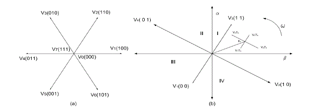
| 1) Intrinsic Voltage Vectors of FSTI: Two among the three phase terminals of the motor are connected to the FSTPI
legs, while the third one is connected to the middle point of the dc-bus voltage. The voltage vectors of the FSTPI have
unbalanced amplitudes and are phase shifted by an angle of π/2 . Indeed, the vectors V1 and V3have the same amplitude
with magnitude of Vdc/√6 while vectors V2 and V4 have the same amplitude with a magnitude of Vdc/√2. The balanced voltage
vectors of the SSTPI and unbalanced voltage vectors of FSTPI and corresponding switching states of the inverter
switches are shown in Fig. 1. |
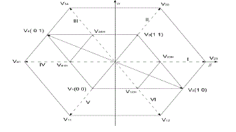
| 2) Generation of Balanced Voltage Vectors from FSTPI Voltage Vectors: The six balanced voltage vectors of the
SSTPI are generated using four unbalanced voltage vectors of the FSTPI. Thus emulates the whole SSTPI voltage
vectors by switching the appropriate four FSTPI voltage vectors. The generated voltage vectors have the same
amplitude and angular shift as those of the SSTPI. Based on the relationship between the balanced voltage vectors of
the SSTPI and unbalanced voltage vectors of the FSTPI, the active voltage vectors Vk is the resultant of the any
adjacent voltage vectors of the four voltage vectors of the FSTPI. The generated balanced six active voltage vectors
V11,V12,V23,V33,V34 and V41 are illustrated in the Fig. 2. |
| 3) Vector Selection Table of the New Strategy: The three level torque controller in the conventional DTC is replaced
by two level torque controller thereby reduce the switching frequency as well as the torque ripple. Each voltage vector
of the SSTPI is obtained by applying suitable combination of the unbalanced voltage vectors of the FSTPI. In order to
emulate the operation of the SSTPI, each control combination (c φ, c τ) should be maintained during two sampling
periods 2Ts. Implemented voltage vector selection table is shown in Table I . It is to be noted that both intrinsic and
compounded voltage vectors are involved in sectors I, III, IV, and VI, while the sectors II and V, only the compounded
voltage vectors are applied. Hence there may be an increase of the switching frequency in sectors II and V, with respect
to the one in the remaining sectors. |
| C. Fuzzy Logic Based DTC
FLC is one of the Artificial Intelligence methods have found vast applications in most of the nonlinear systems like the
electric motor drive. FLC can be used as controller for any system without requirements of the system mathematical
model unlike that of the conventional electric drive control, which uses the mathematical model.Fuzzy Logic is an
intelligent controller and its design do not depend on accurate mathematical model of the system and they can handle
non-linearity of arbitrary intricacy. Among different intelligent algorithms fuzzy logic is the simplest which does not
necessitate intensive mathematical analysis. Fuzzy Logic, unlike Boolean or crisp logic, deals with problems that have
vagueness, uncertainty. Thus here the PI speed controller is replaced by fuzzy logic controller for getting better
dynamic responses. In drive operation, the speed can be controlled indirectly by controlling the torque which, for the
normal operating region, is directly proportional to the voltage to frequency ratio. |
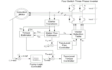
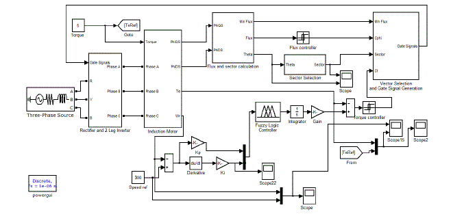
| The schematic diagram of fuzzy logic based FSTPI-fed DTC strategy of induction motor is shown in Fig. 3. Usually
the speed is controlled by PI controller and here PI controller is replaced by fuzzy logic controller whose output is the
torque reference. The fuzzy logic controller is proposed to control the speed of the motor to be constant when the load
varies. The speed error E and change of speed error CE are processed through the fuzzy logic controller whose output
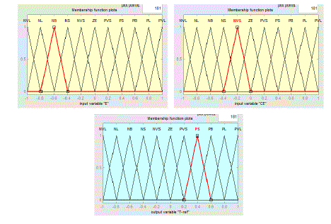
is the torque reference and it compared with the actual torque for the production of torque error. Triangular
Membership functions were constructed to represent the input and output variables as shown in Fig. 4. |
| The speed error and the change in speed error are processed through the fuzzy logic controller whose output is the
torque command. Consider the fuzzy speed control system, where the input signals are E and CE and the output is
torque reference are fuzzified by assigning corresponding membership functions to each signal.The fuzzy sets are as
follows: Z = Zero, PVS = Positive Very Small, NVS = Negative Very Small, PS = Positive Small, NS = Negative
Small, PB = Positive Big, NB = Negative Big, PL = Positive Large, NL = Negative Large, PVL = Positive Very Large,
NVL = Negative Very Large. The universe of discourse of all the variables, covering the whole region, is expressed in
per unit values. The universe of discourse of inputs and outputs of the FLC are chosen between -1 and 1. There are eleven membership functions for E and CE whereas eleven membership functions for the output. Hence there may be
11*11 = 121 possible rules in the matrix. Table II shows the corresponding rule table for the speed controller. The top
row and left column of the matrix indicate the fuzzy sets of the variables E and CE respectively and the output of the
fuzzy controller is shown in the body of the matrix. |
SIMULATION STUDIES AND COMPARISON |
| Simulations of basic DTC, FSTPI-fed DTC and fuzzy logic based FSTPI-fed DTC are carried out for evaluating the
performance of each DTC scheme using MATLAB Simulink. There are many benefits of simulation in the process of
analysis, design and evaluation of power converters.The Induction motor parameters and ratings are shown in Table III. |
| The band width of the stator flux controller and electromagnetic torque controller is equal to ±0.02Wb and ±0.04Nm
respectively. The dc bus voltage is limited to 400V for the sake of safe operation of the inverter.Normally one goes
about the simulation procedure by bringing in fundamental blocks from the library and suitably interconnecting them to
perform the task of a subsystem. It is possible to use this subsystem obtained by grouping these fundamental blocks as
a single block wherever such a subsystem is to be connected. Various subsystem blocks so generated are interconnected
to simulate the entire system.The amplitude of equivalent voltage vectors generated by FSTPI is the half of the one of
the voltage vectors generated by SSTPI. |
| A. FLC based FSTPI-fed DTC
The speed and torque responses at steady state operation of the IM under the control of the basic DTC strategy of
induction motor, for a speed of 300rpm and a constant load torque Tl=5 Nm is obtained from Simulation in MATLAB
Simulink which is shown in Fig. 5. |
| B. FSTPI-fed DTC Strategy
Simulation and analysis of the FSTPI-fed induction motor is done in MATLAB Simulink. The speed and torque
response characterizing the steady state operation of the IM under the control of the FSTPI-fed DTC of IM drive for a
speed of 300rpm and a constant load torque Tl=5 Nm are shown in Fig. 6. The initial transients of torque and torque
ripple of FSTPI-fed DTC are reduced in some extend than that of the basic DTC of IM drives |
| C. FLC based FSTPI-fed DTC
Simulation of fuzzy logic based FSTPI-fed DTC of induction motor is done in MATLAB Simulink and analysed
waveforms. The speed and torque responses characterizing the steady state operation of the IM under the control of the
proposed DTC strategy, for a speed of 300rpm and a constant load torque Tl=5 Nm are shown in Fig. 9. The torque
response curve of each DTC strategy shows that torque ripples and the initial hike of the torque curve are reduced in
considerable amount in the strategy having fuzzy logic controller. The fuzzy logic controller block and FSTPI-fed
fuzzy logic based DTC of IM in MATLAB Simulink are shown in Fig.7 and Fig. 8 respectively. |
CONCLUSION |
| Direct Torque Control is a dominating control technique for induction motor among several control techniques. Its
principles and basic concepts have been introduced and thoroughly explained. It is clear from the explanations that the method of direct torque control also allows the decoupled control of motor torque and motor stator flux. According to
the analysis, the DTC strategy is simpler to implement than the flux vector control method because it does not require
voltage modulators and co-ordinate transformations and it reduces undesired torque ripple. This thesis mainly describes
the analysis of conventional DTC, DTC of FSTPI fed induction motor and fuzzy logic based DTC. Simulations of
various types of DTC are done in MATLAB by emulating the voltage vectors of SSTPI form the voltage vectors of
FSTPI. Fuzzy logic based controller is used to reduce the torque ripple and it was reduced in considerable percentage.
Simulation results show the validity of the fuzzy logic based DTC and it achieves a considerable reduction in torque
and flux ripple signal as well as initial hike of torque almost avoided. |
ACKNOWLEDGMENT |
| I wish to express my sincere gratitude towards myguide & Head of the Department, Prof. Mary George for her valuable
suggestions and support.I would like to express my sincere thanks toProf.Vijayakumari C.K., P.G co-ordinator for their
valuable advice and support throughout my thesis work.I also thank all other faculty members of Electrical Engineering
Department for their wholehearted encouragement and support.I acknowledge the grace and power of Almighty God
without whose blessings none of this would have been possible. |
| |
Tables at a glance |
|
|
| |
Figures at a glance |
 |
 |
 |
 |
 |
| Figure 1 |
Figure 2 |
Figure 3 |
Figure 4 |
Figure 5 |
 |
 |
 |
 |
| Figure 6 |
Figure 7 |
Figure 8 |
Figure 9 |
|
| |
References |
- Takahashi, Isao, and Toshihiko Noguchi. "A new quick-response and high-efficiency control strategy of an induction motor." Industry Applications, IEEE Transactions on 5 (1986): 820-827.
- El Badsi, Bassem, BadiiBouzidi, and Ahmed Masmoudi. "DTC scheme for a four-switch inverter-fed induction motor emulating the sixswitch inverter operation." Power Electronics, IEEE Transactions on 28.7 (2013): 3528-3538.
- Zhang, Yongchang, and Jianguo Zhu. "Direct torque control of permanent magnet synchronous motor with reduced torque ripple and commutation frequency." Power Electronics, IEEE Transactions on 26.1 (2011): 235-248
- Taheri, Asghar, AbdolrezaRahmati, and ShahriyarKaboli. "Efficiency improvement in DTC of Six-phase induction machine by adaptive gradient descent of flux." Power Electronics, IEEE Transactions on 27.3 (2012): 1552-1562.
- Kang, Jun-Koo, Dae-Woong Chung, and Seung-Ki Sul. "Direct torque control of induction machine with variable amplitude control of flux and torque hysteresis bands." Electric Machines and Drives, 1999. International Conference IEMD'99. IEEE, 1999.
- Beltrao de Rossiter Correa, Mauricio, et al. "A general PWM strategy for four-switch three-phase inverters." Power Electronics, IEEE Transactions on 21.6 (2006): 1618-1627.
- Wang, Rui, Jin Zhao, and Yang Liu. "A comprehensive investigation of four-switch three-phase voltage source inverter based on double Fourier integral analysis." Power Electronics, IEEE Transactions on 26.10 (2011): 2774-2787
- Zhang, Yongchang, et al. "An improved direct torque control for three-level inverter-fed induction motor sensorless drive." Power Electronics, IEEE Transactions on 27.3 (2012): 1502-1513.
- Bose, Bimal K. Modern power electronics and AC drives. Vol. 123. USA: Prentice Hall, 2002.
|