Integrated industrial plant fireplace and gas surveillance system using Zigbee is designed to monitor fire and gas leakage and population density in the hazardous locations within the Petroleum refinery. The existing system detects any fire or any gas leakage with in geographically distributed areas. Increase in the complexity of process industry leads to increase in the number of instruments to detect fire and leak. This increases the number of cables that run from industrial sensors to the control station. This increases the bulk of the channel. Troubleshooting the reduced insulation or any wire open is difficult because it is a messy wiring and identifying the individual cable is very difficult along the duct. This also increases the system cost in terms of cable cost. So to cope up with the modern technology it is proposed to have a wireless communication between field devices and the control room. With the advent of wireless technology many parameters can be sent over a single communication medium. This reduces the messy wiring and making trouble shoot easy. The field device can be a portable or a fixed device which communicates the various parameters that are being monitored, to the control room through Zigbee protocol.
Keywords |
| Zigbee, Fire and gas leakage, Troubleshooting, Labview, GPS, RF transceiver, Sensors, LEL, UEL. |
INTRODUCTION |
| Integrated refinery fire and gas surveillance system using Zigbee is a system based on a wireless communication to enhance
man and machine safety in a petrochemical industry. In today‟s world petrochemical industry although being the largest
process control industry it is also highly prone to major fire and gas disasters. A petrochemical industry has excessively
high amount of crude oil stored within a confined area. Therefore presence of any external source which can cause heat or
fire would lead to a major disaster. Even the gases that are present in petroleum refineries are hazardous. |
| The Bhopal gas tragedy which claimed lives of nearly 3,787 people which is one of the major accidents due to gas leakage.
And another instance, the Vishakhapatnam, HPCL refinery disaster claimed lives of 30 people. Though a gas and fire
detection system was present which is connected to the sensors using large number of wires that run from the control room
to various plant areas? But during the fire the wire itself got damaged, so the information did not reach the control room.
So in order to avoid any hazard due fire and gas leakage in a petrochemical industry we have designed an integrated system
which will monitor timely gas leakage in any area around the plant using ZigBee which is a wireless communication
device. We have also proposed a new system which monitors human density within the plant area. Therefore Integrated
plant safety monitor system based on ZigBee can realize workers attendance registration, Real-time precise positioning,
Dynamic gas concentration monitoring, Real-time data transmission & Danger alarm. This system is focused on
implementing the newly designed integrated system in CPCL, Manali. |
LITERATURE SURVEY |
| G.A.Arun Kumar et al [1] proposed the system hardware for gas leakage detection and accurate location identification
system for the production safety in any risky Industries. The detection and location are implemented based on Wireless
Sensor Networks (WSN). However, formerly the system was developed using Virtual Instrumentation. Based on Zigbee
and ARM7, the system is easy to be deployed and overcomes the shortcomings on current systems. Using number of nodes
at different places of risky areas, this system can detect the leakage of gas and immediately sends the details of that location
to the observer. It is used to improve the rescue quality and shorten the time for rescue. Therefore it can compensate for the
weaknesses of existing systems. |
| Dr.Shaik Meeravali and Anusha [3] have developed a gas leak detection and location system for the production safety in
Petrochemical Industry. The system is based on Wireless Sensor Networks (WSN). It can collect the data of monitoring
sites wirelessly and sent to the computer to update values in the location software. Consequently, it can give a real-time
detective of the potential risk area, collect the data of a leak accident and locate the leakage point. However the former
systems can not react in time even cannot obtain data from an accident and locate accurately. The paper has three parts,
first, gives the overall system design, and then provides the approaches on both hardware and software to achieve it. |
EXISTING SYSTEM |
| The existing system only detects the fire and gas leakage in certain important areas only. In existing system, the fire and gas
leaks are measured and the communication is through wires to the control station. In case of faults like discontinuity in
cables, lead to loosing of vital information related to plant safety. Increase in the complexity of process industry leads to
increase in the number of instruments to detect fire and leakage. This increases the number of cables that run from
industrial sensors to the control station which leads to messy wiring. This also increases the size of the duct.
Troubleshooting the reduced insulation or any wire open is difficult because it is a messy wiring and identifying the
individual cable is very difficult along the duct. This also increases the cable cost. |
Limitations of Existing System |
| The fire and gas system is generally required to be independent of the control system. This is consistent with the fire and
gas system normally having a higher integrity requirement than the control system. Some fire and gas systems contain
integrated with emergency shut-down systems. This remains a contentious point. As already mentioned, no single company
can supply all the „best in show‟ products for all the items described in this paper. There are normally interfaces between
different suppliers. Minimizing interfaces, document sets and inspections can be achieved by procuring all products from
one source at the cost of reducing choice of initiating devices and possibly increasing the initial purchase cost. |
| Field interfaces for smoke detectors, heat detectors and manual call-points are generally two wires with modifying
components in the control system or marshalling cabinets to allow a 4-20ma interface to be used. Any failure in the loop
causes the system to fail. Presently, the location of the personals working in the site is uncertain. In case of a dangerous
event, the Control station officers have to personally check the positions of the workers in the particular sites. This calls for
more effort and time. |
Feasible Solution |
| To overcome these difficulties we implemented a portable device. This device can be fixed in their helmet or jacket. To
measure various parameters this device consists of sensors. They are Gas sensor, Temperature sensor, Heart beat sensor,
Pressure sensor. These sensors in the portables device sense various parameters (gas, temperature, pressure) continuously.
And if the value exceeds the reference value, immediately it activates the relay driver and produces an alarming sound. So
it will be useful for the person to know about hazardous situation. Heart beat sensor, senses the workers heart beat
continuously. If the person loses his/her consciousness then this information is sensed by the sensor and it will be passed to
the control room. |
| All the communications are done by wireless Zigbee protocols, so that the information will be transmitted without any
obstructions. The main advantage of Zigbee is that it is a multimode communication, so that the data‟s are transmitted node
by node. A GPS is used in our system to track the location of the person during hazardous conditions, so that he can be
rescued immediately. Finally, all the parameters are monitored using Labview software. It contains a comprehensive set of
tools for acquiring, analyzing, displaying, and storing data, as well as tools to help you troubleshoot code you write. The
main objectives of the fire and gas system are to protect personnel, environment, and plant (including equipment and
structures). The Fire &Gas System shall achieve these objectives by: |
| • Detecting at premature stage, the presence of flammable gas, |
| • Detecting at an early stage, the liquid spill (LPG and LNG), |
| • Detecting incipient fire and the presence of fire, |
| • Providing automatic activation of the fire protection system and automatic shutdown of equipment, |
| • Initiate environmental changes to keep liquids below their flash point, |
| • Initiating wireless signals, both audible and visible as required, to warn of the detected hazards. |
PROPOSED SYSTEM |
| In this system, we are going to monitor and transmit the industrial parameters such as gas leakage and fire. These
parameters are monitored using gas sensor and fire detectors. The analog outputs are converted into digital form using
analog to digital converter and then given to microcontroller. These data are sent to the control room through a Zigbee
wireless via UART also displayed in the LCD display for workers. Corresponding to the sensor outputs the relay is
activated using microcontroller to operate the precaution devices. With this a buzzer alert is also given. In the receiver side
a PC is used to view all the parameter conditions. The relays can be activated from the remote area too via Zigbee wireless
communication. In addition to this, this system integrates person locating with gas concentration checking system
effectively, and realizes functions of person attendance, distance measurement positioning, gas concentration detecting and
data communication. This system is an open system, and it permits developing different applications thereon. It provides a
lot of spatial gas concentration knowledge with the timestamp for follow-up gas prediction research. |
| The field device can be a fixed device or a portable device. The portable device is carried by the worker whenever he enters
the plant area. It is mainly detects the gas leakage if any, wherever the worker goes, it also sends the information about the
location of the person and the heartbeat of the person. The fixed device is fixed in the plant area. It also detects gas leakage
and transmits information to the control room. The system will be developed in Lab view software. The hardware will be
interfaced with Lab view to collect the transmitted data and the interpretation of the received information. This integrated
system was accepted by CPCL and to be developed and tested in their site. We are sure that this system will definitely help
CPCL to increase its safe operation. |
General Architecture of Proposed System |
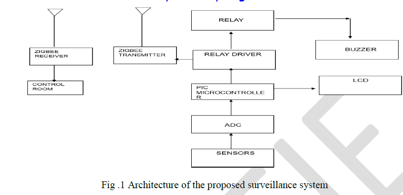
| The general block diagram of the proposed system is shown in fig 1. It refers where the analog parameters like the Gas
leakage, temperature level, pressure level & heartbeat of a worker from the plant area is sensed by the sensors. These
analog signals are sent to the analog to digital converter and a digital signal is further sent to the PIC microcontroller. |
| The microcontroller is programmed in order to transmit these signals to various output devices. The relay drive drives the
relay which sets the buzzer on. The LCD provides the direct information in case of any hazardous situation. The portable
section transmits this information through the Zigbee transmitter to the control room where it is receiver by the Zigbee
receiver and the information is displayed on the PC |
Signal Flow Structure of Portable Unit |
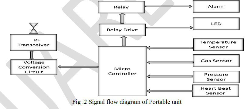
| The portable unit is the unit which the worker carries with him whenever he enters the plant area. The Elements of the
portable unit is shown in fig 2. It can be attached to the helmet or a badge as per convenience. |
| The transportable unit consists of the analog detectors specifically the gas sensor, the temperature detector, the pressure
detector and also the heart beat detector whose output is fed into the microcontroller. The microcontroller sends the
information and through the voltage conversion unit it is sent to the RF transceiver which transmits the signals wirelessly to
the receiving RF transceiver at the control room. |
| The microcontroller can be programmed to send out an alarm through an alarm or an LED. The alarm cannot be driven
directly by the microcontroller and thus a relay is used for this purpose. The microcontroller is connected to a relay drive
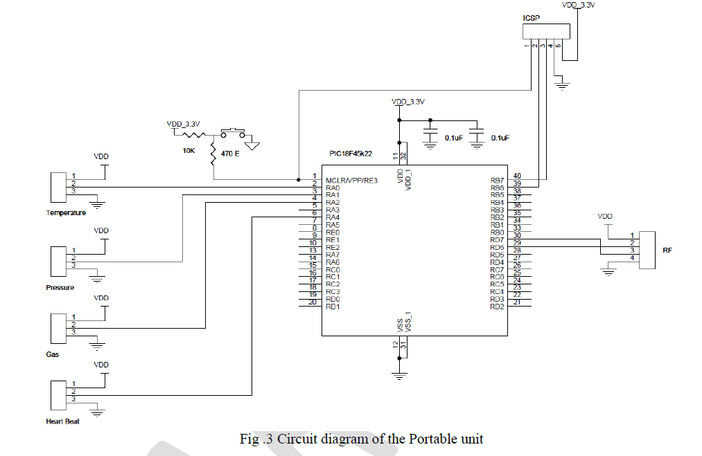
which drives the relay which in turn activates the alarm. The portable unit circuit consists of the four sensors namely
temperature sensor(LM35), pressure sensor(MPX5050), gas sensor(MQ-5) and heart beat sensor(HRM 2115), microcontroller (PIC18F45K22), the RF transmitter, the In Circuit Serial Programmer (ICSP), push button, power supply
and ground as shown in Fig 3. |
| The temperature sensor, pressure sensor and the gas sensor are analog sensors and thus are connected to the analog pins in
the port A, RA0, RA1, RA2 respectively. The heart beat sensor is a digital sensor and is connected to pin RA4 of port A
which is a digital pin. Each sensor has three pins each Vcc (power dc), Vout (analog / digital) and GND (power ground).
The microcontroller used is PIC18F45K22, a 40pin IC which has an inbuilt ADC in it thus the analog outputs can be
directly fed into the microcontroller without getting it through a separate ADC unit. The RF transmitter is used for
communication purpose. It uses a UART which has two parts – a transmitting section and a receiving section. The RF in
this circuit is the transmitting section. Pin 1 of the RF is the power, pin 2 is connected to pin 30 of the microcontroller
which is the transmitting line, pin 3 is connected to pin 29 of the microcontroller which is the receiving line and pin 4 is the
ground pin. |
Receiver Section and Output Devices |
| The receiving end of the system, as shown in Fig 4 consists of a RF transceiver, a voltage conversion unit, a USB interface
and a PC. The RF transceiver serves the purpose of receiving the signals that are transmitted by the portable or the fixed
device through the Zigbee network to the receiving end at the control room. The voltage conversion unit is used for the
conversion of the incoming signal into voltage that is compatible with the PC. A USB interface is used to interface this
signal into the PC. |
| An output device is any piece of computer hardware equipment used to communicate the results of data processing carried
out by an information processing system (computer) which converts the electronically generated information into humanreadable
form. They are Alarm, Liquid Crystal Display and Computer. An alarm device or system of alarm devices offers a
sounding, visual or different type of alarm signal a couple of drawback or condition. Alarm devices square measure
typically outfitted with a siren. |
PERFORMANCE ANALYSIS OF PROPOSED SURVEILLANCE SYSTEM |
Analysis of various wireless Devices |
| A comparison between the various wireless communication devices is given in Table1. The Zigbee having a long battery
life consumes less power, a higher network capacity than the other devices. |
| The communication distance is less; this is because a mesh network is used in the network topology and the communication
distance is between the nodes and thus can be used in a long range. The speed is comparatively low this drawback is
bearable for the proposed system as the parameters are being monitoring only in specified time intervals as any gas leakage
reaches its UEL levels only gradually and not in split seconds. |
Analysis of various Gas LELs and UELs |
| The Lower Emission Level (LEL) and Upper Emission Level (UEL) of the various gases are discussed in Table 2. The LEL
is the Level of gas in percentage below which the gas is not hazardous or does not catch fire; the UEL is the upper level of
gas leakage above which it is not flammable. |
RESULT AND DICUSSION |
| Thus, an industrial safety system is designed and constructed for workers working in hazardous environments, comprising
of two sections. A portable unit is provided to the workers, which is capable of sensing hazardous conditions like gases,
excessive temperature and humidity etc. and a monitoring system which interacts with the portable unit using a Zigbee
wireless communication link. |
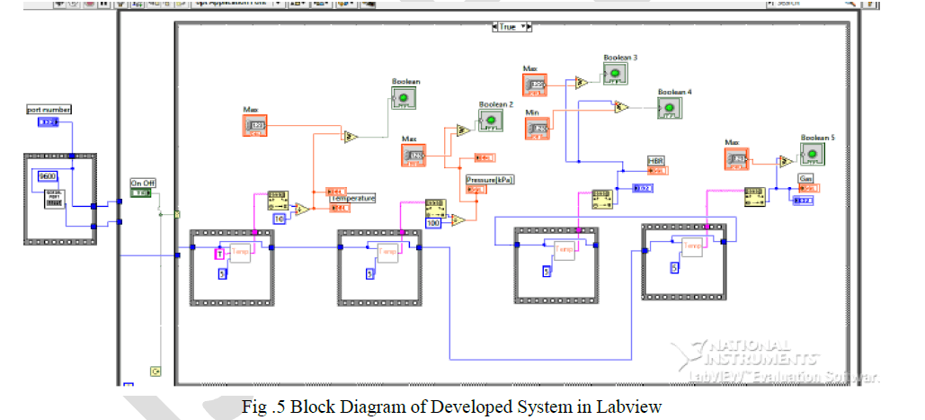
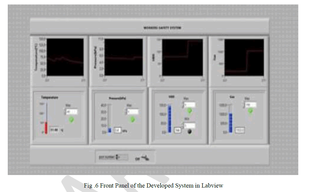
| The block diagram developed in Labview for the proposed monitoring system is shown in fig.5. This proposed system
detects the fire and gas leakage in all part of the plant instead of important areas. Fig.6 illustrates the front panel of the
developed system in Lab VIEW. The digital indicators indicate the output from various sensors implemented in the system.
If the outputs of the sensors exceed the set point, the LED flashes. The plot depicts the variation of output with respect to
time. |
| So the developed system in Labview can be enhanced by adding a control element which controls the gas leakage if it
exceeds the specified upper explosive level for the various gases in the plant area. This can be achieved by any gas leakage
indication in any part of the plant alerts the control room and then the control valve is shut off. Therefore preventing any
hazard arising due to gas leakage. |
Advantages of the developed system in Labview |
| • Communication channel availability is maximized. |
| • Workers distribution at any given time for any area is known. |
| • Open system, allows developing other applications. |
| • Long time archiving helps analysis. |
| • Safety system integrity is improved. |
CONCLUSION |
| The proposed Surveillance system to detect Fire and Gas Leakage using Zigbee protocol is developed to enhance man and
machine safety in a petroleum refinery. The main objective of the system was early detection of gas leakage around the
plant area. With the detection of a gas leak the sensor present in the plant area as well as with the plant area workers alerts
the control room personnel. Therefore with this system even the human density in the plant area was determined. We have
also analyzed various wireless technologies and various hardware and software approaches that can be implemented. After
implementing this system in petrochemical industry, it was found out to be more efficient than the previously existing
system. And with the introduction of Zigbee the whole project cost was also reduced and human safety level was also
increased. |
Tables at a glance |
 |
 |
| Table 1 |
Table 2 |
|
| |
Figures at a glance |
 |
 |
 |
 |
 |
 |
| Figure 4 |
Figure 5 |
Figure 6 |
|
| |
References |
- ArunKumar.G.A., Rajasekhar.K., Satyanarayana.B.V.V., and SuryanarayanaMurthy.K, âÃâ¬ÃÅImplementation of Real time Detection of Gas leakage in Industries usingARM7 &ZigbeeâÃâ¬ÃÂ, International Journal of Engineering Research & Technology, Vol .1, Issue 7, pp 1-4, Sep 2012
- Chih-Ning Huang, Chia-Tai Chan, âÃâ¬ÃÅZigBee-based indoor location system by k-nearest neighbor algorithm with weighted RSSIâÃâ¬ÃÂ, Procedia Computer Science, Volume 5, pp.58-65, 2011.
- Dr.ShaikMeeravali and Anusha, âÃâ¬ÃÅDetection Of Gas Leak And Its Location Using Wireless SensorsâÃâ¬ÃÂ, Vol.1, Issue 9, pp.1-8, November 2012.
- Ebrahim.A. Soujeri,Harikrishnan.A.I, Rahim Rajan,Sumi.M, âÃâ¬ÃÅDesign of a zigbee-based RFID network for industry applicationsâÃâ¬ÃÂ, proceedings of the 2nd international conference on Security of information and networks, pp.111-116, 2009.
- Fabio Graziosi, FortunatoSantucci, Marco Di Renzo, Stefano Tennina, âÃâ¬ÃÅLocating zigbee nodes using the tiscc2431 location engine: a testbedlatform and new solutions for positioning estimation of wsns in dynamic indoor environmentsâÃâ¬ÃÂ, Proceedings of the first ACM international workshop on Mobile entity localization and tracking in GPS-less environments, pp.37-42, 2008.
- Jeffrey Wong, HaruoNoma, Kiyoshi Kogure, Masakazu Miyamae, Satoshi Takahashi, ShojiroNishio, TomojiToriyama, Tsutomu Terada, âÃâ¬ÃÅA ZigBee-based sensor node for tracking people's locationsâÃâ¬ÃÂ, proceedings of the 2nd ACM international conference on Context-awareness for selfmanaging systems, pp. 34-38, 2008.
- Jin Hyung Park, Joon Goo Park, Sharly Joana Halder, Sin Woo Park, Sung Hun Kang, Tae Young Choi, âÃâ¬ÃÅEnhanced ranging using adaptive filter of ZIGBEE RSSI and LQI measurementâÃâ¬ÃÂ, Proceedings of the 10th International Conference on Information Integration and Web-based Applications & Services, pp.367-373.2008.
- MSA Gas detection hand book, 2008 8 Protection Analysis Eric William Scharpf, The Instrumentation, Systems, and Automation Society (May 1,2002) Year of Publication: 2012.
|