ISSN ONLINE(2319-8753)PRINT(2347-6710)
ISSN ONLINE(2319-8753)PRINT(2347-6710)
| A. M. Shirahatti Associate Professor, Department of Mechanical Engineering, Maratha Mandal Engineering College, Belgaum, Karnataka, India |
| Related article at Pubmed, Scholar Google |
Visit for more related articles at International Journal of Innovative Research in Science, Engineering and Technology
The suspension system plays a major role in any automobile as far as the vehicle stability and ride comfort of the passengers are considered. In conventional or passive suspension systems performance parameters like ride comfort, road holding and suspension travel, are mutually contradicting while active suspension system has the potential to improve these factors. The present work aims to study a full vehicle model having passive and active suspension system subjected to random road profile as per ISO standards. The linear quadratic controller (LQR) is used for active suspension system. Using optimization procedure the actuator force, which minimizes the performance index is determined. Passenger ride comfort is directly related to the passenger seat acceleration and road holding relates to wheel displacement and suspension travel. The active suspension system performance is compared with passive suspension system subjected to random road profile. Results show passenger bounce and acceleration are reduced drastically in active suspension system indicating improvement in both road holding and comfort.
Keywords |
| Active suspension, ride comfort, road holding, LQR control, random road |
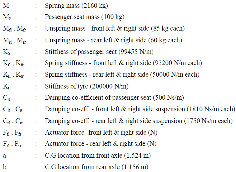
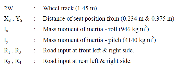
NOMENCLATURE |
 |
 |
I. INTRODUCTION |
| Vehicle suspensions have been a hot research topic for many years due to its important role in ride comfort, vehicle safety, road holding and the overall vehicle performance. To meet these requirements, many types of suspension systems, ranging from passive, semi-active and active suspensions, are currently being employed and studied [1]. Over the years, the development of active suspension systems has gained a significant momentum in vehicle design activities. Compared with passive system, generally constructed with the selection of springs and dampers, the active suspension system offers a greater capability to control the system behavior by detecting appropriate state variables in a specified control scheme [2]. With rapid advances in electronic technologies, it becomes increasingly feasible to realize an active suspension system. Consequently, ride comfort and road handling quality can be greatly improved by applying suitable control schemes without excessively degrading the compactness of suspension working space. |
| The control scheme plays a pivotal role in active suspension design to achieve superior ride and road handling qualities. The objective of controller is to achieve optimal combinations of road holding, ride comfort and power consumption. Different design criteria are defined either in frequency or time domain for controllers and large variety are devised. The commonly approaches are proportional-integral-derivative (PID) [3-6], model-predictive control (MPC) [7, 8], load dependent controller [9], fuzzy logic [10-13], neural network [10, 14], H∞ [15-17], LQR [10, 18-21], Skyhook controller [10, 22], preview controller [23, 24] etc. More details about this methods can be found on [25]. |
| The present work aims to study a full vehicle model having passive and active suspension system subjected to random road profile as per ISO standards [26, 27]. The linear quadratic controller (LQR) is used for active suspension system. This involves optimization procedure which consists of determining the control output i.e., actuator force, which minimizes the performance index. The limitation of controller input and requirement of performance characteristic are represented by the performance index. The control forces at the front and rear ends are included in the performance index to represent indirectly the vertical, pitch and roll motion. |
II. MATHEMATICAL MODEL OF FULL VEHICLE |
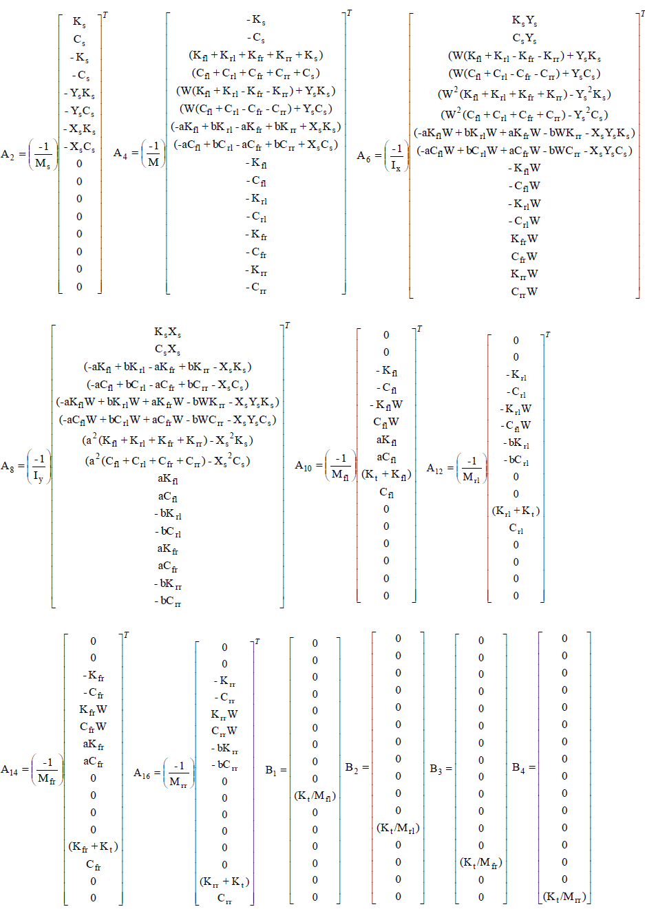
| Figure 1 shows full vehicle model with 8 DOFs considered for analysis [25]. The equations of motion for complete model are as follows. |
 |
 |
 |
 |
ACTIVE SUSPENSION |
| The eqn. 9 describe linear time invariant (LTI) system and it is assumed that for the controller design all the states are available and could be measured accurately. A state variable feedback regulator is considered first [28]; |
| F =-KX (10) |
| Where K represents the feedback gain matrix. |
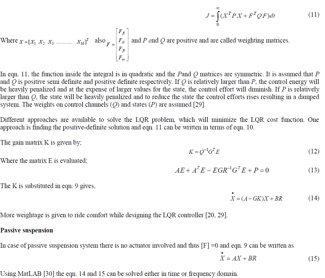
| The control input F should be optimized such that the performance index is minimized. The performance index is represented by J which will take care of limitations of controller input and requirement of performance characteristic. In the current work linear quadratic controller is used. Using optimization procedure the actuator force F, which minimizes J [25, 29] is determined. |
 |
IV. RANDOM ROAD PROFILE |
| A random road exciting function is used as input to the vehicle model. The major characteristic of a random function is uncertainty in predicting an exact value at a future time and hence the function should be described in terms of probability statements as statistical averages. |
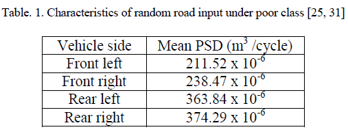
| The ISO has proposed road roughness classification based on the power spectral density values [26, 27, 31]. Table 1 and fig. 2 illustrates the stochastical characteristics of the measured random input used for analysing the system, which corresponds to the poor road condition as being classified by ISO. |
 |
 |
V. RESULTS AND DISCUSSION |
| In the analysis of system response with random road input, limits are assigned for all the states, passenger acceleration and actuator force in order to satisfy the required ride comfort, road handling and the design restriction. These limits are |
 |
| Since, all the state variables, acceleration and control force have been constrained the problem of controller design is then a challenge for finding suitable weightings that satisfies the design performances. This can be done by trying arbitrary weighting matrices R and Q. |
| Figures 3-6 illustrates clearly how the active suspension can effectively absorb the vehicle vibration in comparison with passive suspension. Figures 3(a) and 3(b) shows the seat displacement and acceleration respectively for both suspension system. It is found that maximum seat displacement is reduced from 0.03m to 0.002m while maximum seat acceleration was reduced to 1.7 m/s2 from maximum value of 10.9 m/s2. |
 |
| Also, sprung mass vertical, pitch and acceleration displacements are reduced drastically in case of active suspension compare to passive suspension system (see fig. 4). The overall passenger seat displacement and acceleration are reduced significantly using active suspension, which guarantee better ride comfort. Moreover, suspension travel and tyre displacement are also reduced (see fig. 5 and 6). |
 |
| For quantitative comparison, since the road input to the system is in the form of normal random distribution, it is expected to have normal distributed outputs. Therefore, using the concept of variance for the output signals, one can calculate useful probability values for the values. For a Gaussian normal distribution, the probability function of the random signal x(t) can be written as [31]; |
 |
| Where σ is the standard deviation (STD), λ is a real number, (erf) denotes error function and (erfc) denotes complementary error function. The numerical values for the probability function are illustrated in table 3. The table below presents numerical values associated with λ = 1, 2, and 3. |
 |
| For each state variable the bounding limit with 90% probability is calculated. This quantity can be evaluated by using standard deviation of the signal together with eqn. 16 and 17. Let (erf) -1 represents the inverse error function. Hence, eqn. 17 will transform to; |
 |
 |
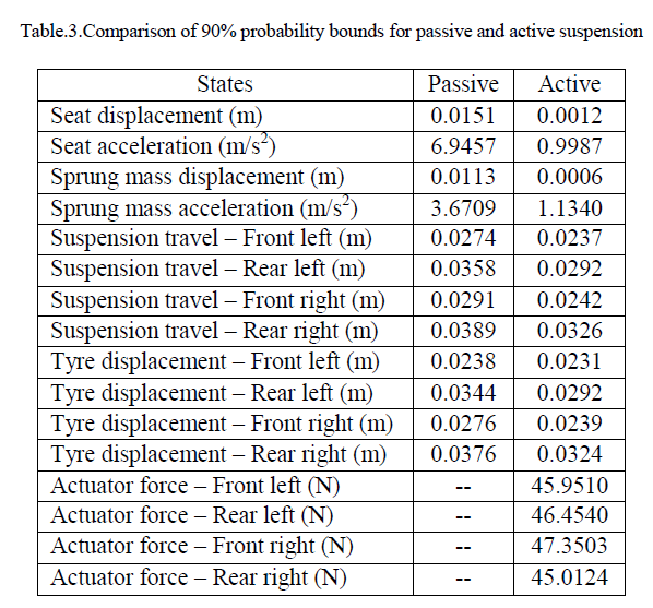
| Table 3 illustrates the system variables bounds with 90% probability for passive and both active suspensions. In this statistical comparison it is shown that the passenger seat and passenger acceleration in active case are reduced drastically (92% & 86%) their values in passive suspension system. Also there is drastic reduction in sprung mass displacement and acceleration (95% & 69%). The tyre displacement and suspension travel are slightly reduced for active suspension system by 13.8% and 18.4% respectively compare to passive suspension system. This confirms the efficiency of the active suspension in both ride comfort and road handling performance. |
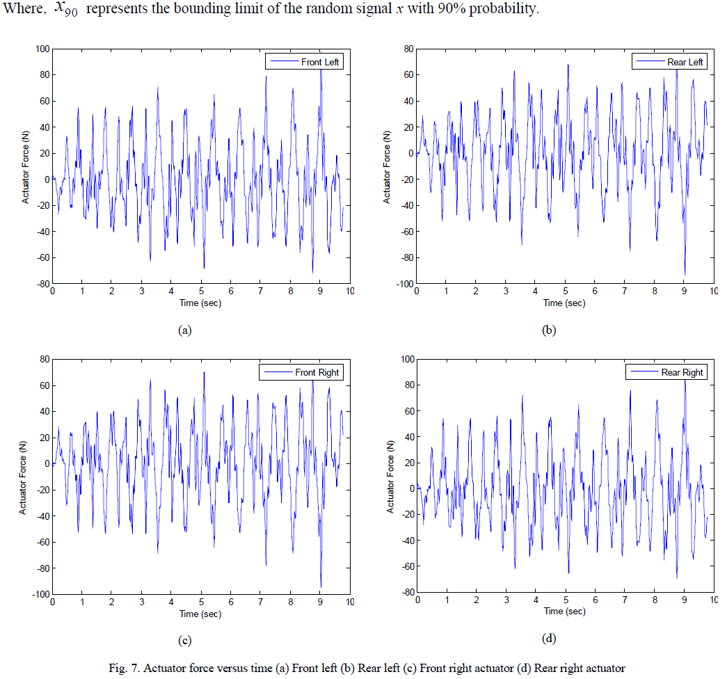
| Figure 7 gives the plots between control force required and time and it is found that the actuator forces are well below the practically implementable limits. The quantitative values in table 3 could be an effective tool for the designer to satisfy the required performance or to compare different designs. |
 |
VI. CONCLUSIONS |
| The primary purpose of this paper is to design and simulate an LQR controller based active suspension for full vehicle model with 8DOF, which improves the performance of the suspension with respect to design goals compared to passive suspension. Measured random road surface which as per ISO road classification falls under poor category of road is used as input to full vehicle model. Passenger seat displacement, passenger seat acceleration, suspension travel and tyre displacement is used to evaluate the performance of active and passive suspensions. Limits are assigned for all state variables, passenger acceleration and also actuator forces in order to satisfy the design goals. By analysing the response it is observed that all variables satisfy the constraints. A stochastical technique has been used for quantitative comparison the LQR controller design approach of active system with respect to passive system, in which for each variable the amount of bounding limit with 90% probability is calculated. From the simulation results for random road input, it is evident that the passenger seat bounce and passenger acceleration in active case are reduced by 92% & 86% respectively while tyre displacement and suspension travel are reduced by 13.8% and 18.4% respectively compared to passive suspension system. This confirms the efficiency of the active suspension in both ride comfort and road handling performance. |
ACKNOWLEDGEMENT |
| The author is gratefully acknowledge Mr. M. M. Kulkarni, Vehicle Research Development Establishment, Ahmednagar, Mr. A. C. Mattikalli and Mr. A. M. Hulagabali of MMEC, Belgaum for their valuable suggestions. The author would also like to thankMrs. Rajshree N. Halgekar (President, Maratha Mandal), Dr. Uday S. Hampannavar (Principal, MMEC) and Prof. C. S. Wadageri (HOD, Mechanical) for their encouragement for the research work. |
References |
|