ISSN ONLINE(2319-8753)PRINT(2347-6710)
ISSN ONLINE(2319-8753)PRINT(2347-6710)
Jatinder Kaur1, Kamaljeet Kaur2, Gurpreet Singh Brar 3, Monika Bharti4
|
| Related article at Pubmed, Scholar Google |
Visit for more related articles at International Journal of Innovative Research in Science, Engineering and Technology
The root-locus method is a well-known tool for control system analysis and design. It is an important topic in introductory undergraduate engineering control disciplines. In this paper we present the analysis of a transfer function using root locus method. Through analysis of transfer function we check the effect of gain on poles and zeros.
Keywords |
| Transfer function, Damping ratio, Feedback |
INTRODUCTION |
| The root locus gives the closed-loop pole trajectories as a function of the feedback gain k. Root loci are used to study the effects of varying feedback gains on closed-loop pole locations. In turn, these locations provide indirect an idea about stability and transient response of a closed-loop system. The Root locus is a powerful technique as it displays the entire dynamic response of the system. And hence is extensively used in control engineering. |
 |
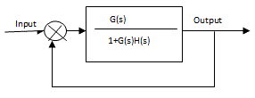
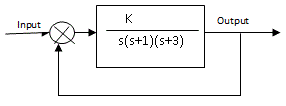
| The root locus is a powerful tool for designing and analyzing feedback control system, it is a graphical method by determining the locus of roots in the s-plane as one system parameter is changed. Root Locus plots are a method of evaluating the behavior of a control system. The creation of a root locus plot begins by determining the poles of the control system for a given set of control parameters. These poles are then plotted on a complex coordinate system as seen in the previous section and analyzed to determine the behavior of the system. In addition to determining the stability of the system, the root locus can be used to design the damping ratio and natural frequency of a feedback system. Root locus plots show the roots of the systems characteristic equation as a function of the control variables. In this paper we consider a unity feedback control system with transfer function and then determine the value of k at different damping ratio values. Damping ratio represents the locus of poles. |
 |
LITERATURE REVIEW |
| A novel approach has been implemented for plotting complementary root locus using only the well-known root-locus construction rules. It has been analyzed that complementary root locus can be plotted using only the well-known construction rules to plot root Locus. A Theorem applied to plot the complementary root locus when, using only the traditional complementary root-locus construction rules (Teixeira et al., 2004). An attempt has been made for plotting the root-loci for the linear control system with delay in control or in state. The path of the root-locus plot shifted from neighborhoods of the open-loop zeros instead of the open-loop poles and it was observed that the effect of time-delay was easily handled (Suh and Bien, 1982). The effect of the frequency domain Quantitative Feedback Theory (QFT) technique has been incestegated on the root-locus. A case study was demonstrated which demonstrate the better understanding of the power of the QFT technique. The guide lines was provided for a successful root-locus design (Bossert, 1993). An effort has been used to update the existing root-locus technique for linear finite-dimensional systems and adapted to the case of systems with time delay. An example has been demonstrated to validate the purposed root loci of time-delay systems in simple manner. (Yeung and Wong, 1982). An analytical procedure has been implemented for obtaining the root locus with positive and negative gain is described. The path of root locus with respect to time constant was investigated. The gain or time constant was computed for each point on the root locus. It has been concluded that purposed method for obtaining the root locus with respect to time constant is simple than graphical method (Chang, 1965). |
SIMULATION RESULT |
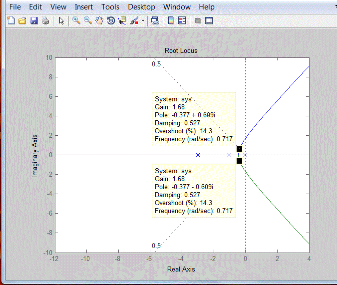
| In fig.3, corresponding to damping ratio 0.527, and roots of -0.377±0.609i, the value of gain which we have obtained is 1.68.In above figure the solid lines (Root Locus) tells that how the two closed loop poles move when k is varied. Then we determine the values of gain at different roots and different damping ratio shown in table 1. Table 1 result depicts as damping ratio decreases, the gain factor increases. From table 1, we concluded that as gain increases the poles on same axis starts move away. Through root locus analysis, we also determine the frequency values at different gain factors. |
 |
CONCLUSION |
| The results reported in this paper suggest that for making system more stable, the main fact is the position of poles and number of poles. If we consider the number of poles fact, then it should be essential that number of poles always greater than number of zero’s. The other thing which we noticed from our results is that as k is increased, the two poles split and move away. |
References |
|