Keywords
|
| BLDC motor, Four Switch Three Phase Inverter, Sensor-less control, Low Cost. |
INTRODUCTION
|
| Permanent-magnet brushless dc (BLDC) motor is increasingly being used in automotive, computer, industrial and household products because of its high efficiency, high torque, ease of control and lower maintenance. A BLDC motor is designed to utilize the trapezoidal back EMF with square wave currents to generate the constant torque. A conventional BLDC motor drive is generally implemented via a 3 phase six switch inverter and Hall-effect position sensors that provide six commutation instants for each electrical cycle. As the cost of conventional BLDC drive systems are very high the efficient BLDC motor cannot be used in low cost applications. The use of 6 switch inverter increases conduction losses as well as the cost of the drive system. The four switch inverter used in the proposed system helps in reducing conduction losses and cost, moreover as two switches are eliminated the current drawn by the inverter is less compared to conventional 6 switch inverter [1]. The motor driven by a 4 switch inverter as 6 working modes. |
| In BLDC motors only two phases are active at a time and the stator are commutated with respect to rotor position. The mechanical hall sensors used to detect rotor position in conventional drive system are temperature sensitive. The output of these hall sensors are affected by the temperature of the surroundings and thus system reliability is reduced. Mounting of these mechanical sensors in the motor is difficult and it increases the weight of the system. In proposed drive system the rotor position is detected using position sensorless scheme. Researches on increasing the reliability and reducing the cost of the drive system lead to development of different position sensorless schemes [3]. The position sensorless scheme used in proposed drive system is based on back EMF zero crossing [4]. The back EMFs of different phase is obtained from three terminal voltage differences. This position sensorless control used in proposed drive system increase system reliability as it is not affected by surrounding temperature. The cost of BLDC motor without hall sensors are very low compared to conventional BLDC motor. |
| As proposed drive systems has reduced components a different control system should be used to achieve the desired characteristics without performance degradation. The control approach used in proposed drive system employs speed control and current control using single current sensor [5]. The PI (Proportional-Integral) controller is used as speed controller due to its simple structure and ease of design. The current control is used to limit the current mainly in modes involving phase C. A simple PWM generator is used to generate the PWM signals to excite the switches. Thus reduction in the number of power switches, switching driver circuits, losses and total price are the main features of the proposed drive system. |
PROPOSED LOW COST BLDC DRIVE SYSTEM
|
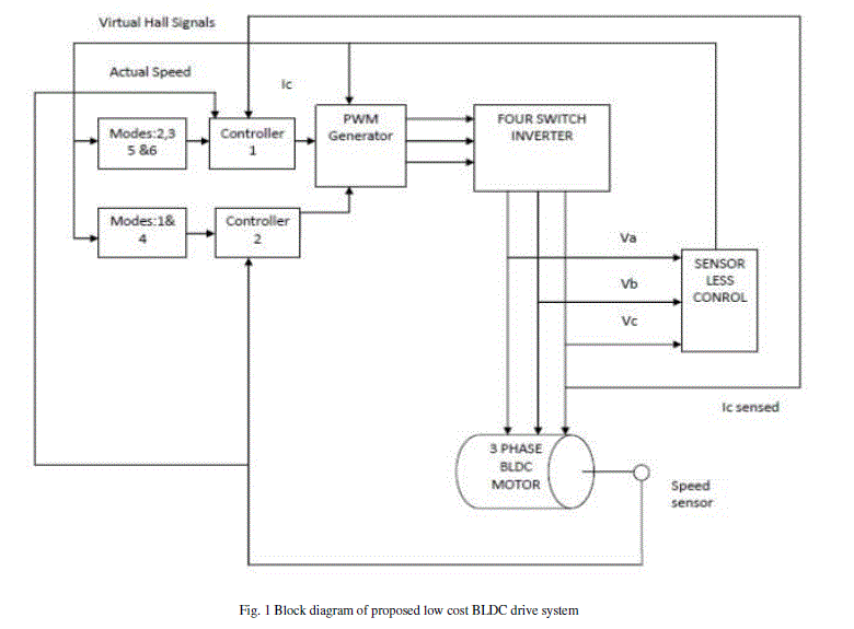
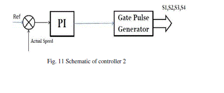
| A simplified block diagram of the proposed drive system is shown in Fig. 1.The BLDC motor is electronically commutated using a four switch inverter. PWM generator generates the appropriate PWM signals for the 4 switch inverter. The rotor position is detected using a position sensor less scheme which generates virtual hall signals. The virtual hall signals generated resembles the actual hall signals obtained from mechanical hall sensors. The motor has 6 different operating modes. From Virtual hall signals the working mode is analysed and according to the mode controller 1 or controller 2 operates. The control system employed has a double loop structure. Controller 1 is operated when phase C is involved, controller 1 has speed control and current control. The inner current loop maintains the rectangular current waveforms and outer speed loop maintains the desired characteristics of the system. A single current sensor is used for hysteresis current control .The speed control is attained using a PI controller. Controller 2 is a PI controller which is used to attain speed control during mode 1and 4. A speed sensor is used to detect actual speed of the motor |
WORKING OF FOUR SWITCH INVERTER DRIVEN BLDC MOTOR
|
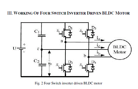
| Fig. 2 show a four switch inverter driven BLDC motor. As shown in Fig 2, two common capacitors are used instead a pair of bridges As phase C is connected to midpoint of dc link capacitors it’s not controllable. In BLDC motors only two phases are conducting at a time and other phase is inactive. A four switch driven BLDC motor has 6 working modes as shown in table below. Phase C is active during modes 2, 3, 5 and 6. Only 1 switch is operated in these 4 modes as phase C is out of control [2]. The BLDC motor is supplied by the whole dc bus only during modes 1 and 4.The output voltage will be restricted in all the modes involving phase C as only half of the DC link voltage comes across the motor. |
| Mode:1 |
| From the table I we can understand that in mode: 1, the switches operated are and . The capacitors are charged during this mode .Phase A and B are active in this mode |
| Mode:2 |
| Now capacitors are fully charged, with positive charge on upper plate and negative charge on lower plate. Phases A and C are active in this mode. As phase C is involved only one switch is operated in this mode. Current enters through , then flow through phase A winding and returns through phase C winding and capacitor .Current won’t return through , as upper plate of is positive |
| Mode:3 |
| This mode is almost similar to mode: 2. Negative current flows through phase C. In this mode other phase involved is phase B, therefore is operated. |
| Mode:4 |
| In this mode, the full dc link voltage comes across the motor. The capacitors again get charged during this mode. Phases A and B are active during this mode. Switches and are operated in this mode. |
| Mode:5 |
| Phase C is active in this mode so only switch is controlled in this mode. The current enters the phase C winding through as its upper plate is positive and returns through phase A winding and switch .The current is as shown in Fig 7. |
| Mode:6 |
| Phases C and B are active in this mode. Current flows from lower capacitor to phase C and returns through phase B. |
THEORY OF POSITION SENSORLESS SCHEME
|
| The proposed position sensorless scheme is based on detection of back EMF zero crossing from terminal voltage difference. Consider a BLDC motor whose stator windings are connected in star. The BLDC motor is driven by a four switch inverter whose windings are triggered with respect to rotor position as explained in section III. The phase A terminal voltage with respect to star point of stator is given by |
 |
| Van =Terminal phase A voltage with respect to star point |
| L = Equivalent Inductance of the winding |
| R = Equivalent Resistance of the winding |
| Rectangular shaped phase A current Trapezoidal shaped back EMF |
| Similarly for other two phases terminal voltage is given by |
 |
 |
| From these terminal voltages, the line voltages can be determined as |
 |
| Similarly and |
 |
 |
| Can be determined by subtracting equations 5 and 6: |
 |
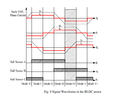
| Fig 9 shows signal waveforms generated by a four switch inverter driven BLDC motor explained in section III. Consider mode 4, the shaded region where a and b are conducting and c is open. In this interval = , and and are equal and opposite. So equation 7 can be simplified as |
 |
| Similarly |
 |
 |
| It is evident from the Fig 9 that in mode 4 the back EMF of phase C transients from one polarity to another zero crossing .The phase c is excited after a phase shift after the zero crossing instant of .The zero crossing points of back EMFs can be determined indirectly from line voltage difference. The back EMF obtained indirectly by terminal voltage difference is opposite to actual back EMF .So while generating virtual hall signals the value of hall signal is 1 if the value obtained from the equations 8,9 and 10 are less than or equal to zero. The terminal voltage difference is obtained and voltage difference is filtered to avoid unwanted zero crossing points. A Low pass filter is used for filtering. Zero crossing is detected and according to the value of back EMF the virtual hall signals are generated using a virtual hall signals maker circuit. The performance of this position sensorless scheme can be analyzed with simulation results in the section VI. |
CONTROL SYSTEM
|
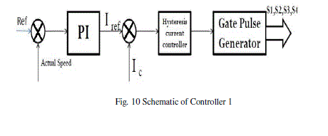
| The control system has a double loop structure. Current control is done with hysteresis current control to maintain the rectangular current waveforms .Speed control is attained using pi controller. Two controllers are used in the proposed drive system. Controller 1 is used in modes where phase C is involved, the schematic of controller1 is shown in Fig 10. |
| As phase C is out of control the current in these modes should be limited. Current of phase C is sensed using a single current sensor and controlled. As current in all phases shoots up equally the use of single current sensor enables us to limit current in other phases also. But in modes 1 and 4 Ic is zero, so current control cannot be attained in these modes. Current in the phases of motor won’t shoot up instantly so this won’t affect the performance of the proposed drive system. The schematic of controller 2 is as shown in Fig 11. |
| Depending upon the virtual hall signals, PWM generator generates appropriate signals for the switches to obtain smooth working of the motor. The output signals of the controller given to the PWM generator determines for how much time the respective switches should be turned on. |
SIMULATION RESULTS
|
| The performance of proposed low cost drive system can be analyzed with the help of simulation results. The simulation models is established using MATLAB/SIMULINK..The parameters of BLDC motor used in simulation are listed in table II. |
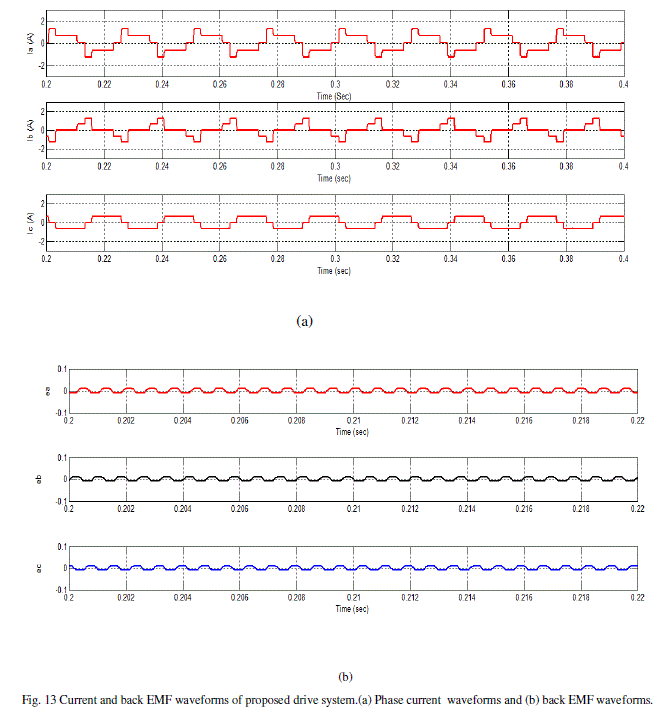
| The current and back EMF waveforms obtained using simulink model is shown in Fig 13. By observing the current waveforms we can conclude that the phase c current has quasi square shape as obtained in conventional drive systems. The current in phases A and B is increased at some points because in modes 1 and 4 current control is limited. But this won’t affect the characteristics of the drive system. The quasi square waveforms of phase currents using proposed method proves that a cost effective BLDC drive system with reduced components can give the desired characteristics as in conventional drive systems. The trapezoidal back EMFs is also obtained with the proposed drive system. The waveforms in Fig 13 show the good controllability of proposed BLDC drive system. |
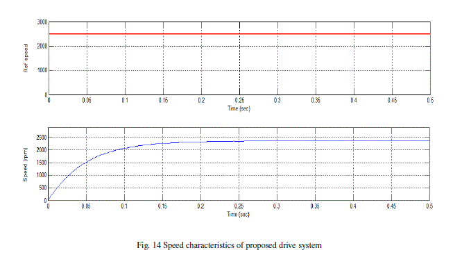
| Speed Characteristics are shown in Fig 14.The waveform shows that smooth speed control is obtained in the proposed drive system using PI controller. The speed control is limited in lower range as filtering is done in position sensorless scheme. The waveform shown in Fig 14 shows that the actual speed and the reference speed is almost same. |
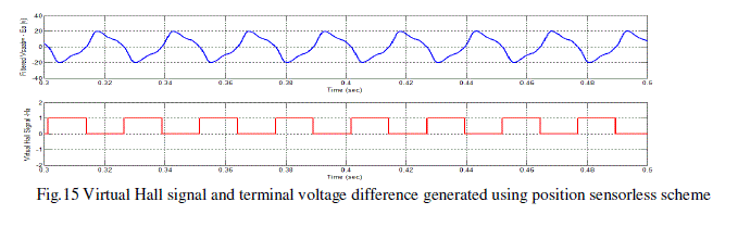
| The position sensorless scheme used in proposed drive was evaluated using simulation results. The filtered terminal voltage determined resembles the negative of back EMF waveform, so hall signals are generated only when the filtered terminal voltage is less than or equal to zero. The waveform of filtered terminal voltage and virtual hall signal is shown in Fig 15.The virtual hall signal is exact to those produced by mechanical hall sensors in conventional drive systems. |
CONCLUSION
|
| The paper presents simulation of a new low cost BLDC drive system without performance degradation. Cost minimization is achieved by using 4 switch inverter and implementing position sensorless control. Apart from cost saving the use of four switch inverter helps in reducing conduction losses. As sensorless control is used to detect rotor position the system reliability is increased. The control system involving single current sensor gives satisfying current waveforms .The speed can be controlled over a wide range, from 20 % of full speed to full speed using a PI controller. From simulation results we can understand that the proposed drive system with reduced components gives the characteristics of the conventional high cost BLDC drive system. So with the development of these cost effective BLDC drive system the efficient BLDC motor can also be used in low cost application |
Tables at a glance
|
 |
 |
| Table 1 |
Table 2 |
|
| |
Figures at a glance
|
 |
 |
 |
 |
| Figure 1 |
Figure 2 |
Figure 9 |
Figure 10 |
 |
 |
 |
 |
| Figure 11 |
Figure 13 |
Figure 14 |
Figure 15 |
|
| |
References
|
- D.-H. Jung and I.-J. Ha, “Low-cost sensorless control of brushless DC motors using a frequency-independent phase shifter", IEEE Trans. Power Electron, vol.15, no.4, pp. 744-752, Jul. 2000.
- V.Krishnakumar and Dr. S. Jeevanandhan, “Four Switch Three Phase Inverter Control of BLDC ,” 2011 1st International Conference on Electrical Energy Systems, Pages 139-144, Jun. 2011.
- P. P. Acarnley and J. F. Watson, “Review of position- sensorless operation of brush-less permanent-magnet machines ", IEEE Trans. Ind. Electron.,vol 53, no. 2, pp. 352-362, Apr. 2006.
- P .Damodharan and Krishna Vasudevan, “Sensorless Brushless DC Motor Drive Based on the Zero-Crossing Detection of Back Electromotive Force (EMF) From the Line Voltage Difference,” IEEE Trans on energy conversion , VOL. 25, NO. 3, September 2010.
- C. Xia, Z. Li, and T. Shi , “A Control Strategy for Four-Switch Three-Phase Brushless DC Motor Using Single Current Sensor,“ IEEE Trans Ind. Electron., vol. 26, no. 6, pp. 2058–2066, Jun. 2009.
- Mohsen Ebadpour ,M. B. B. Sharifian and Mohammad Reza Feyzian, “A Simple Position Sensorless Control Strategy for Four-Switch Three- Phase Brushless DC Motor Drives Using Single Current Sensor,” 2nd Power Electronics, Drive Systems and Technologies Conference, Pages 235-240,Feb. 2011.
|