ISSN ONLINE(2319-8753)PRINT(2347-6710)
ISSN ONLINE(2319-8753)PRINT(2347-6710)
Ganapathy Srinivasan. R1, Sevvel. P 2, Mohanraj. L3
|
| Related article at Pubmed, Scholar Google |
Visit for more related articles at International Journal of Innovative Research in Science, Engineering and Technology
Composite materials are made up of two or more materials on a macroscopic scale. Polymer matrix composites are plastics (resins) within which there are embedded fibres. The plastic is known as the matrix, and the fibres orientated within it are known as the reinforcement. The reinforcement tends to be stiffer and stronger than the matrix providing stiffness and strength. Reinforcement is laid in a particular direction, within the matrix, so that the resulting material will have different properties in different directions i.e. composites have anisotropic properties. This characteristic is exploited to optimise the design and provide high mechanical performance where it is needed
INTRODUCTION |
| The primary reason why polymer matrix composites are chosen for the manufacture of components is due to the weight saving relative to their stiffness and strength. For example carbon fibre reinforced composite can be five times stronger than some grades of steel while having only one fifth the weight. Polymer matrix composites as with all engineering materials have specific advantages and limitations. The development of composites has been driven by the need to produce materials with improved mechanical, temperature and chemical resistance properties over currently available engineering materials. The specific stiffness or strength of a material can be defined by dividing by the material density. It is these very good specific properties of composites that allow the design of high performance structural components. Polymer composite material structures are also engineered so that the directional properties of the reinforcement are capable of resisting the loading on a given component or structure. In addition, polymer composites are useful in applications where the environmental conditions would be detrimental to other materials. A wide selection of polymeric materials and reinforcement systems are available to match appropriate environmental conditions. Inevitably, the mandate for the use of polymer composite materials, or that matter any material will be dictated by the balance of cost against performance in a given application Polymer matrix composites can be used for metal replacement, but there are key property differences which mean that direct substitution should be subject to material selection via a materials expert. |
| Engineering materials in general are isotropic having the same properties such as strength and modulus, in any direction. Boundary 'grain' may be present in some metals due manufacture but it is only in critical applications that this needs consideration. Composites, however, are anisotropic and will have very different properties in different directions since the matrix material is isotropic, but the reinforcement is not. Carbon fibres can be as much as 100 times stronger under tension than they are in shear, and the stiffness may differ in the two directions by similar ratios. The properties of the composite will reflect the properties of the reinforcement, so that it can have greatly different properties in different directions. This is exploited in design as components and structure rarely require equal strength and stiffness in all directions, and composites can achieve this by particular arrangements of the reinforcement. |
II. COMPOSITE TYPES |
| There are a relatively small number of polymer types that can be utilised in the fabrication of a composite. However, it must be remembered that within each class many grade variations exist. The selection of any polymer system will be a function of the design criteria including operating environment, cost, fibre type and manufacturing method. The common resins available include: |
2.1 Polyester |
| Polyester usually dissolved in styrene to reduce its viscosity for ease of fabrication. A catalyst such as organic peroxide is added to produce polymerization (solidification) with the application of heat around 100°C to 160°C. The material exhibit significant mould shrinkage, which can be reduced by the addition of a thermoplastic additive. Polyester is a widely used matrix material, generally in conjunction with glass fibre reinforcement. It is used primarily for low performance applications and has limited high temperature performance. Strong bonding between the matrix and glass fibre can be achieved provided a silane coupling agent is used. Other types of reinforcement fibre are generally not used because of inadequate bonding to the resin. |
2.2 Vinyl Ester |
| Vinyl esters are dissolved in styrene in order to reduce viscosity and facilitate fabrication into a composite structure. Catalysts are required to cure the material. No additional agents are required in order to produce high adhesion to glass fibres. The product has more flexibility and greater fracture toughness than a polyester resin. Heat deflection temperatures up to 200°C can be obtained. |
2.3 Epoxy |
| A liquid resin which is cured by the addition of a curing agent at room or higher temperature conditions. Epoxy resins have a wide range of properties. They can be rigid or flexible with different temperature resistance, with some able to withstand continuous use up to 250°C. Advantages of epoxy resins over polyester and vinyl ester resins include lower mould shrinkage, low volatility during curing, good environmental and solvent resistance, and very good adhesion to most reinforcement materials. They are widely used in structural aerospace applications. |
2.4 Bismaleimide |
| Bismaleimide can exist in solution or hot-melt resin form. These materials have high temperature resistance and withstand temperatures of 300°C. When used with carbon fibre reinforcement they are considered to be advanced composites because they have superior performance to epoxies in hot/wet conditions, but there are limitations. They are normally very brittle and prone to micro-cracking, although, as with epoxies, this tendency can be reduced by the incorporation of a thermoplastic component. |
2.5 Polyimide |
| Polyimide exhibits better performance than bismaleimide in high temperature, wet conditions, and appear to be the most widely used resins for high temperature applications. It should be noted that service temperature will depend strongly on the nature of the application with some grades capable of sustained periods at temperatures over 300°C. The limitation of polyimide is that it is very brittle. The curing mechanism is a condensation reaction. This tends to produce voids in the cured component. Additional reactions can be used instead to reduce or eliminate this problem. |
| Carbon fibre properties depend on the structure of the carbon used. Typically they come defined as standard, intermediate and high modulus fibres. Indicative materials properties are: |
 |
2.6 Aramid fibres |
| have the highest strength to weight ratio compared to other commercially available fibres. Kevlar manufactured by DuPont is one familiar brand name. Aramid fibre exhibits similar tensile strength to glass fibre, but can have modulus at least two times as great. Aramid is very tough allowing significant energy absorption but, compared to carbon, it is lower in compressive strength and has poorer adhesion to the matrix. It is also susceptible to moisture absorption. |
| Aramid fibre properties depend on the structure used and can be tailored for high toughness or high modulus. Indicative materials properties are: |
 |
2.7 Boron fibre |
| Actually predates carbon fibre as a high-modulus reinforcement material. The cost of boron, however, has seen its demise, with its replacement with carbon fibre. They do not differ greatly from glass fibre in tensile strength, but can have modulus five times that of glass. Since the objective of reinforcement is to stiffen, this is a significant advantage. Their use is confined to niche markets, where the modulus advantage over carbon fibre is critical. |
III. FACTORS DETERMINING POLYMER MATRIX COMPOSITE COSTS |
| The factors which determine the direct costs of producing components and structures from polymer matrix composites are: |
| ïÃÆÃË Material costs |
| ïÃÆÃË Tooling costs |
| ïÃÆÃË Finishing costs |
| ïÃÆÃË Processing costs |
| Furthermore other additional costs associated with quality control, health and safety and environmental factors need to be considered. For applications the benefits from using polymer matrix composites can become significant when component-lifetime costs – cradle to grave, rather than just material and fabrication costs, are included. |
3.1 Polymer matrix composite applications |
| The use of polymer matrix composites is diverse and far reaching touching all industry sectors with applications ranging from commercial aircraft to bath tubs. |
| Applications include: |
| Boat decking - boat hulls, submersibles pressure hull, propeller shafts, masts, bulkheads, rudders |
| Transport – car & rail body panels, bumper fascia, radiator grills, instrument panels, engine components, fuel lines |
| Civil engineering – bridges, column wraps, cladding, repair of concrete |
| General engineering – pipe systems, air ductwork, power transmission drive shafts, storage tanks, pressure vessels |
| Aerospace – General & military aviation fuselage, bulkhead & floor, cargo liner, wings, landing gear, doors, rotor blades & hubs, satellite structure |
| Sport – bike frames, canoes, fishing rods, archery bows, golf clubs, ski poles & skis, surf boards, racquets Domestic consumer – sanitary ware – baths & shower units, furniture |
| Furthermore other additional costs associated with quality control, health and safety and environmental factors need to be considered. For applications the benefits from using polymer matrix composites can become significant when component-lifetime costs – cradle to grave, rather than just material and fabrication costs, are included. |
IV. PROCESS SELECTION |
| The Identification of the process route is essential at the earliest stages of design as the process selection, material selection & design features are intimately linked & for practical purposes are inseparable. |
| The benefits to you |
| ïÃâ÷ Maximised process efficiency & quality |
| ïÃâ÷ Total process development, solutions to concept to prototype to product |
| ïÃâ÷ Ensuring process robustness is factored in to new product developments |
| ïÃâ÷ Reduced time to market for new developments |
| ïÃâ÷ No exposure to the risk associated with the capital investment of equipment |
| ïÃâ÷ Informed, impartial advice & support as & when you need it |
| The development of robust process technology is fundamental to the success of any new composite product venture. Drawing on a wealth of experience, covering virtually every sector of the polymer industry, Smithers Rapra can advise on all aspects of the process from tool design & scale up through to a complete line layout. |
| Bespoke processes can be tailored to meet difficult or novel applications & clients can access a well-equipped pilot plant to augment their own Research & Development facilities. In addition, experienced consultants can advise on existing manufacturing issues from process troubleshooting to complete manufacturing audits. |
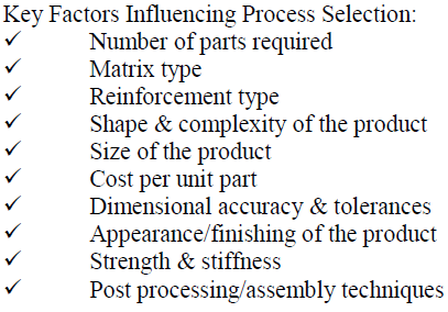
| There is a diverse number of processing routes for composites. Selecting the right process for the product is paramount to its success. It is vital that throughout the design process, there is a fundamental understanding of the range of processes available & their advantages, disadvantages & limitations. For instance a poor design may exclude a more cost effective production route. |
 |
V. INSPECTION AND ANALYSIS |
| In the hull provided for inspection, blisters under the external gel coat ranged in size from a few mm to 25 mm in diameter. Blistering was restricted to the area of the hull below the water line. A cross section of a typical blister reveals a wall thickness of about 1 mm. This is the thickness of the gel coat. The blister fluid was extracted with a hypodermic syringe and was analysed using various techniques. Gas liquid chromatography was used to identify organic solutes. In ascending order of concentration these were established as diethylene glycol, methyl ethyl ketone (MEK), acetic acid, styrene, benzaldehyde. The fluid had a pH of 4.5. Atomic absorption spectroscopy was used to identify and quantify cations. Calcium ion concentration was 1500 ppm, aluminium was at 200 ppm, as was cobalt. |
VI. FAILURE DIAGNOSIS |
| Polyester resins are generally formulated with a glycol. Diethylene glycol or polypropylene glycol tend to be used in standard formulations, whilst others such as 2,2,4-trimethyl1,3-pentanediol or 2,2-dimethyl-1,3-propanediol are preferred for marine grade resins. It is probable therefore that the main laminating resin is a standard orthophthalic polyester containing excess diethylene glycol. Acetic acid, which is mainly responsible for the low pH of the blister fluid, is a by-product of the hydrolysis of polyvinyl acetate. The high concentration would suggest that emulsion bound CSM has been used as the reinforcement. Benzaldehyde is a by-product of the oxidation of styrene. The standard reactive diluent for these resins is styrene monomer. The higher than expected concentration of MEK and cobalt ions is significant. MEK is a soluble breakdown product of methyl ethyl ketone peroxide (MEKP), and MEKP/cobalt (II) is the standard catalyst system for these polyester resins. It is probable that an excess of the catalyst has been used, either by mistake or to facilitate an increase in the cure rate. The high concentration of calcium and aluminium ions is not unusual. E glass contains calcium and aluminium oxides, and these are leached out of the fibres by water and more rapidly by acids. |
| Slow permeation of water through the gel coat is inevitable. Whether this is sufficient to cause eventual blistering depends on many factors. The most important is the availability of water soluble species under the gel coat. Concentrated solutions will trigger an increase in the rate of water permeation by osmosis. In this case the immediate availability of excess cobalt salts and MEK probably initiates the process. The next phase is sustained by the hydrolysis of the polyvinyl acetate emulsion to acetic acid. The final stage is the acid leaching of water soluble metal salts from the glass fibres. These reactions, if sufficiently vigorous, will lead to a solute concentration, increased osmotic pressure, and eventually to blistering. |
VII. CONCLUSION |
| Although the gel coat blistering phenomenon cannot be predicted with confidence, the service conditions, material variables and the fabrication procedures that promote it are reasonably well known within the marine construction industry. However in this case the fabricator had insufficient experience within the sector to avoid the risk of blistering. This should be born in mind when selecting a supplier. Suppliers with a short but successful history of fabricating products for a particular service environment should not be treated as equivalent to those whose products have (demonstrably) stood the test of time. Customers should insist that representative laminates be subjected to accelerated testing to assess blistering resistance. Typically this involves exposure of the gel coat to condensed water at 60 °C for several hundred hours. Resin suppliers will advise as to the level of resistance required for any given application. Warm fresh water is the most detrimental service environment for GRP craft. |
| To defend against blistering in such an environment a powder bound reinforcement mat should have been employed rather than an emulsion bound reinforcement mat. Marine grade resins should have been used for the structural laminate as well as the gel coat. More consideration should have been given to catalyst levels. |
References |
|