ISSN ONLINE(2319-8753)PRINT(2347-6710)
ISSN ONLINE(2319-8753)PRINT(2347-6710)
Anirudh R. Iyer1, R. Venkatachalam2, A. Balaraju3
|
| Related article at Pubmed, Scholar Google |
Visit for more related articles at International Journal of Innovative Research in Science, Engineering and Technology
Suspension system of an automobile not only supports the body of the vehicle, engine and passengers but also absorbs shocks arising from the roughness of the road. Most of the present day cars are provided with independent suspension for the front wheels and conventional suspension for the rear wheels. Such a suspension system is referred in this paper as semi-independent suspension system. When the automobile is moving, the roughness of the road keeps giving excitations to the suspension system through tyres. The stiffness and damping of the suspension system play an important role in absorbing the shocks and provide comfort to the passengers. In this paper, an attempt is made to obtain the optimum values of these parameters for providing maximum comfort to the passengers.
Keywords |
| Semi-independent suspension system, Full car model, Optimum suspension parameters |
INTRODUCTION |
| The suspension system is one of the most important systems of an automobile. Its main purpose is not only to support the engine, its components, passengers, but also to isolate them from shocks arising due to roughness of the road. It has been a practice from the beginning to have a frame called chassis which is being supported through springs and dampers by the front and rear axles. This type of suspension system is called Conventional Suspension System. There is yet another type of suspension called Independent Suspension System, in which the axle of a wheel is hinged to the body and is held in position by springs and dampers which are placed in between axle and the body. There is no separate chassis and the body of the vehicle itself acts as chassis. Many of the present day cars use independent suspension for the front wheels and conventional suspension for the rear wheels. In this paper, such a system is referred as Semi-independent Suspension System. The study of suspension systems has been a subject of interest for many researchers. A suspension system may be modelled as a quarter car model or a half car model or a full car model. The quarter car model or half car model yield the results very quickly but they are not accurate because they do not represent the system in a realistic way because the roll and/or pitch motions cannot be taken into account by these models. Full car model considers the entire vehicle as it is. The results can be considered to be accurate and realistic. However, the analysis becomes more complex. Hedrick [1] considered a quarter car model with hydraulic actuator acting under the effect of coulomb friction. An absorber based nonlinear controller and adaptive nonlinear controller are proposed. Employing two sensors, one for displacement and other for velocity measurements, Majjad [2] considered a quarter car model and estimated the nonlinear damping parameters. Gobbi and Mastin [3], Wei Gao et al. [8] studied dynamic behaviour of passively suspended vehicles running on rough roads. The road profile is considered to give random inputs to the suspension system. Rajalingam and Rakheja [4] studied the dynamic behaviour of quarter car model under nonlinear suspension damper. Ahmed Faheem [5] studied the dynamic behaviour using quarter car model and half car model for different excitations given by the road. Jacquelien et al. [6] used electrical analogy in conjunction with quarter car model and studied the control scheme of the suspension system. Wei Gao et al. [7] also studied the dynamic characteristics considering the mass, damping and tyre stiffness as random variables. Kamalakannan et al. [9] tried adaptive control by varying damping properties according to the road conditions. Sawant et al. [10] developed an experimental procedure for determining the suspension parameters using a quarter car model. Thite [11] refined the quarter car model to include the effect of series stiffness. State space equations are employed to calculate the natural frequency and model damping ratios. Gadhia et al. [12] analysed quarter car model for rear suspension using ADAMS software. Wei Gao et al. [13] investigated dynamic response of cars due to road roughness treating it as random excitation. Lin [14] performed a time domain direct identification for vehicle mass, damping and stiffness. Husiyno Akcay [15] studied multi objective control of half car suspension system. It is observed that when the tyre damping coefficients are precisely estimated, the road holding quality of the suspension system can be improved to some extent. Li-Xing Gao [16] considered a half car model in conjunction with pseudo-excitation for the road conditions and studied the dynamic response of the vehicle. Thite et al. [17] used a frequency domain method for estimating suspension system parameters. Roberto Barbosa [18] studied the frequency response of half car model due to pavement roughness. Roberto Barbosa [19] also investigated vibrations of vehicles subjected to a long wave measured pavement irregularity. |
| Attempts are being made to analyze the four wheeler with fully independent suspension system. Libin Li [20] performed computer simulation studies through multi body model, identifying twenty degrees of freedom. Pater Gaspar [21] considered full car model and proposed a method for identifying suspension parameters taking into account nonlinear nature of the components. Anil Shirahatt et al. [22] attempted to maximize the comfort level considering a full car model. Genetic algorithms have been employed to perform optimization to arrive at optimum values of suspension parameters. Hajkurami et al. [23] studied the frequency response of a full car model as a system of seven degrees of freedom. Ikbal Eski [24] obtained neural network base control system for full car model. Guidaa et al. [25] proposed a method of identifying parameter of a full car model. The analysis has been developed for designing an active suspension system. Balaraju and Venkatachalam analysed the dynamic behaviour of an automobile using full car model for both, fully conventional suspension systems [26] and fully independent suspension systems [27]. In this paper, an attempt is made to study how the values of the stiffness and damping of a semi-independent suspension system affect the comfort level of the passengers. The work in this paper is divided in two stages. 1) Text- Detection 2) Inpainting. Text detection is done by applying morphological open-close and close-open filters and combines the images. Thereafter, gradient is applied to detect the edges followed by thresholding and morphological dilation, erosion operation. Then, connected component labelling is performed to label each object separately. Finally, the set of selection criteria is applied to filter out non text regions. After text detection, text inpainting is accomplished by using exemplar based Inpainting algorithm. Paper is organized as follows. Section II describes automatic text detection using morphological operations, connected component analysis and set of selection or rejection criteria. The flow diagram represents the step of the algorithm. After detection of text, how text region is filled using an Inpainting technique that is given in Section III. Section IV presents experimental results showing results of images tested. Finally, Section V presents conclusion. |
FORMULATION |
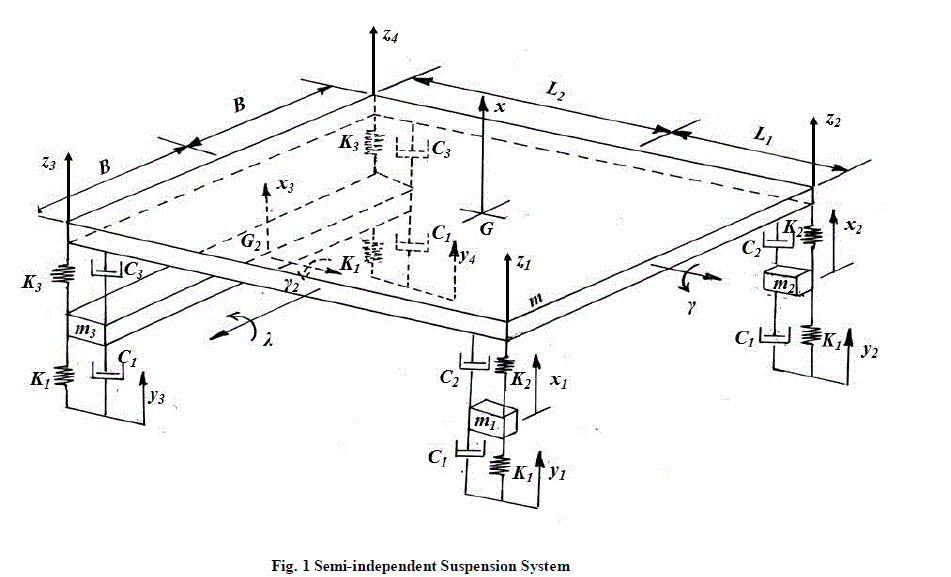
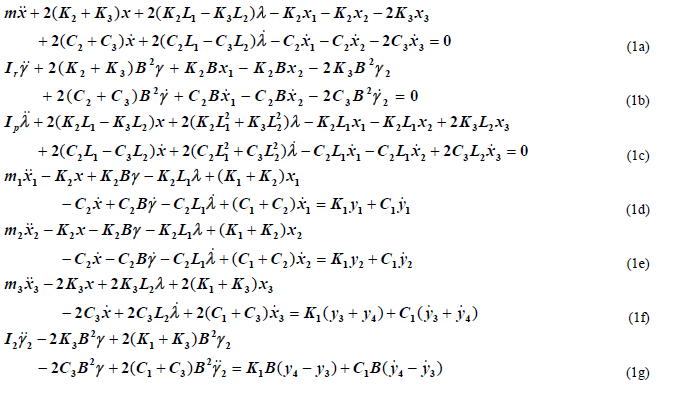
| Figure 1 shows a schematic arrangement of the semi-independent suspension system. It is to be observed that on the front side there is no axle, hence, there are only two masses, m1 and m2 which may represent the masses of the front tyres. It is also to be observed that on the rear side there is a mass m3 , which may be viewed as a mass taking into account the mass of the axle and also masses of the rear tyres. The mass of the main body may be represented by m. G and G2 are the centres of mass of the main body and the rear axle, respectively. The point G is located by the distances B , L1 and L2 as shown in the figure. (K1 ,C1),(K2 ,C2) and (K3 , C3) may represent the stiffness and damping properties of a tyre, front shock absorber and rear shock absorber, respectively. Coordinates x1 and x2 may be used to represent the vertical motions of the masses m1 and m2 , respectively. The rear axle can move up and down and can also exhibit roll motion. Coordinate x3 may represent the vertical motion of G2 , and γ2 may represent the roll motion. The main body can exhibit roll and pitch motions, γ and λ , apart from the vertical motion x of the centre of mass G. In total, the motion of the entire system may be described by seven coordinates, x1 , x2 , x3 , x , γ2 , γ and λ .Thus the system is possessing seven degrees of freedom. It is also to be observed in the figure that the displacements induced by the road profile are indicated by yi , i = 1 to 4 . The equations of motion may be derived as |
 |
 |
ANALYSIS OF THE SUSPENSION SYSTEM |
| Based on a practical road vehicle Santro Xing, numerical values are assigned to various parameters involved, as follows. |
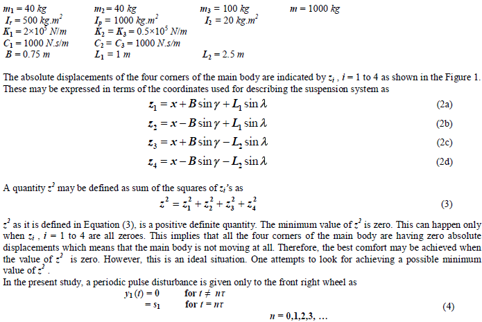 |
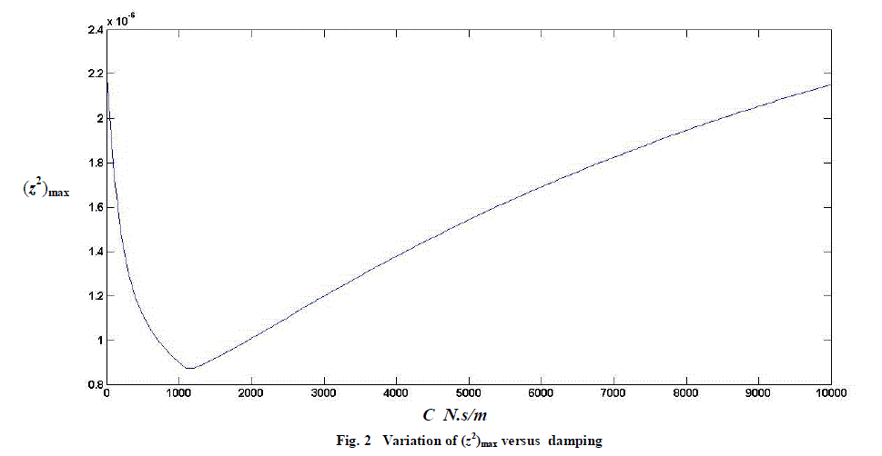
| Taking s1 = 0.1 m and τ = 1.6 s, the equations of motion are integrated and the values of z2 are observed throughout. They are also observed to vary periodically. The maximum value of z2 is noted. A periodic pulse disturbance is preferred because it is expected that it would be convenient and easy to observe the maximum value of z2 . Various parameters except C2 and C3 , are given values as mentioned above. For the present analysis C2 and C3 are taken same value C. The damping C is varied from 0 to 10,000 N.s/m in steps. For each value of damping, the equations of motion are integrated for the disturbance described in Equation (4). The maximum value of z2 is noted for each value of the damping. Figure 2 shows variation of (z2)max with C. It may be observed that for a value of damping around 1000 N.s/m , the value of (z2)max is minimum. The existence of optimum value of damping may be explained as follows. When damping is nearly zero, the system would be an undamped system. Therefore, one can expect large amplitudes of forced vibrations. When damping is very large, it may be realised that the damper is providing a rigid connection of chassis to the axles. Hence, the entire disturbance is directly transferred to the main body. One should allow free movement of the plunger of the damper for pumping out the energy of the system effectively. Therefore, there must exist an optimum value of damping. |
 |
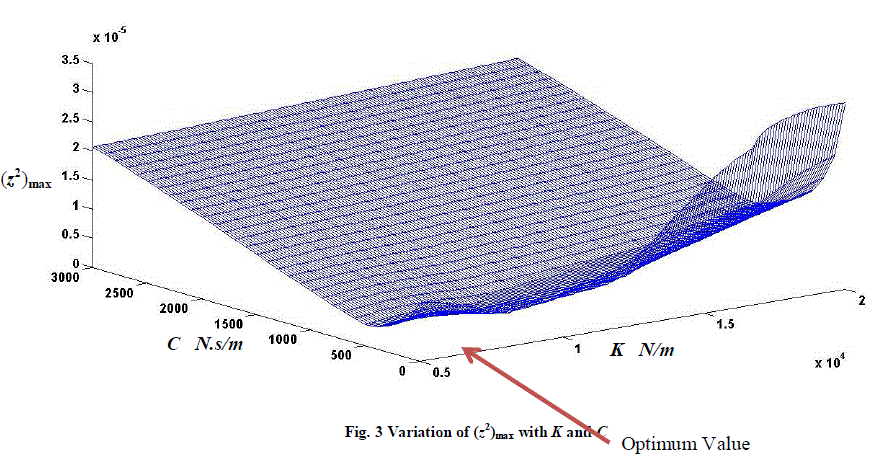
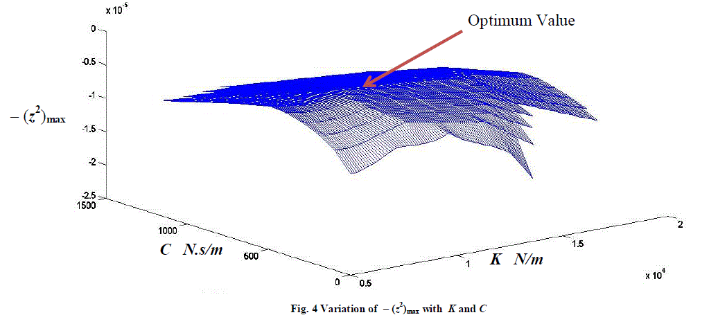
| The springs also play an important role in the vibrations of the main body. As in the case of damper, if the spring stiffness is very large, it would represent a rigid connection. At the same time, the spring cannot take zero stiffness because it is one of the two essential elements of a vibrating system. It is then felt interesting to watch how (z2)max varies when the stiffness and damping are both varied, simultaneously. For the purpose of computations the stiffnesses K2 and K3 are taken same value K. The stiffness and damping are both varied simultaneously in steps and the values of (z2)max are observed. Figure 3 shows a three dimensional plot of (z2)max . It may be observed that the surface obtained is concave, indicating a global minimum. For easy visualization of the optimum point, values of – (z2)max are plotted as in Figure 4. A convex surface makes it convenient to observe the optimum values of the parameters. The optimum values are found to be K2 = K3 = 8300 N/m and C2 = C3 = 700 N.s/m. |
 |
 |
CONCLUDING REMARKS |
| The work presented in this paper and significant conclusions that may be drawn based on the present work may be summarized as follows. |
| (i) A full car model of semi-independent suspension system is studied for optimum parameters of suspension system. |
| (ii) For the purpose of study, the values of various other parameters are taken which correspond to a real practical automobile. |
| (iii) The reason for existence of optimum values for the stiffness and damping parameters is discussed. |
| (iv) A quantity z2 is defined to indicate the comfort level for the passengers. |
| (v) Periodic pulses are given at the right side front wheel and the maximum value of z2 is observed. |
| (vi) The two parameters stiffness and damping are both varied in steps and the variation of (z2)max is observed. |
| (vii) The variation is shown in a three dimensional figure. |
| (viii) The optimum values of the parameters are indicated in the figures. |
References |
|