ISSN ONLINE(2319-8753)PRINT(2347-6710)
ISSN ONLINE(2319-8753)PRINT(2347-6710)
| V.G.Vijaya Department of Mechatronics Engineering, Bharath University, Chennai – 600073, India |
| Related article at Pubmed, Scholar Google |
Visit for more related articles at International Journal of Innovative Research in Science, Engineering and Technology
This project deals with stress analysis of rigid flange couplings subjected to torsion using ansys. The theory related to the title will be studied from ‘FUNDAMENTALS OF MACHINE DESIGN by T.J.PRABHU, page no- 12.3Analytical solution will be obtained. To obtain computer solution ANSYS will be used. A comparison of results obtained from 2 & 3 will be presented.
I.INTRODUCTION |
| A coupling is a device used to connect two shafts together at their ends for the purpose of transmitting power. Rigid flange coupling are designed for heavy loads or industrial equipment. When joining shafts within a machine, mechanics can choose between flexible and rigid couplings. The connecting methods for flange couplings are usually very strong because of either the pressure of the material or the sometimes hazardous nature of materials passed through many industrial piping systems. |
II.DESIGN AND CALCULATION |
Input Parameters |
| Material: Mild Steel |
| Power transmit: 80 kw at 200 rpm |
| Allowable shear stress in shaft: 45 N/mm2 |
| Allowable shear stress for key material: 45 N/mm2 |
| Crushing stress for bolt and key: 160 N/mm2 |
| Shear stress for bolt material: 30 N/mm2 |
| Shear stress for cast iron: 8 N/mm2 |
Calculation |
 |
 |
 |
 |
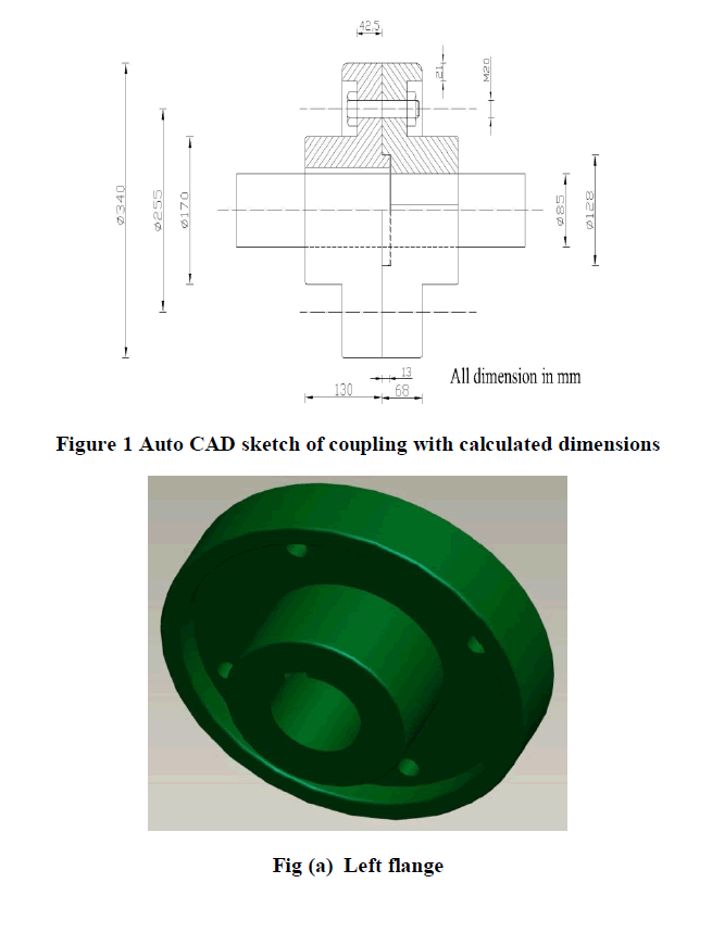 |
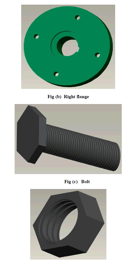 |
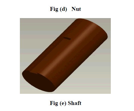 |
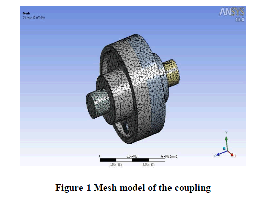
| There are several methods analysis software’s have been used for analyzing. In this project we are using Ansys software for analyzing. Ansys is a leading finite element analysis software developed by ansys inc. it is use friendly graphical user interface package. In a linear static we determine the stresses, displacements, strain and reaction in the fem. Static analysis deals with computation of displacement and stress due to static loads refers to loading but doesn’t cause inertial or damping effects to be significant for consideration in the analysis. The material |
| The material used here is grey cast iron, the Poisson’s Ratio of grey cast iron is 0.28 and the Young's Modulus is 1.1e+005 Mpa |
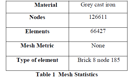 |
 |
 |
 |
IV.CONCLUSION |
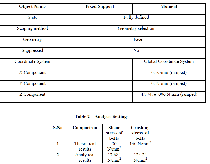
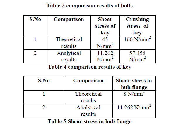
| It was found that the stress obtained from the Ansys software is slightly less than the stress obtained in the theoretical calculation. The shear stress and crushing results obtained from Ansys was compared with the theoretical calculation as tabulated. Hence the results obtained from Ansys matches theoretical calculations so the design is safe |
References |
|