ISSN ONLINE(2319-8753)PRINT(2347-6710)
ISSN ONLINE(2319-8753)PRINT(2347-6710)
Karthik N1, Dr. C Anil Kumar2
|
| Related article at Pubmed, Scholar Google |
Visit for more related articles at International Journal of Innovative Research in Science, Engineering and Technology
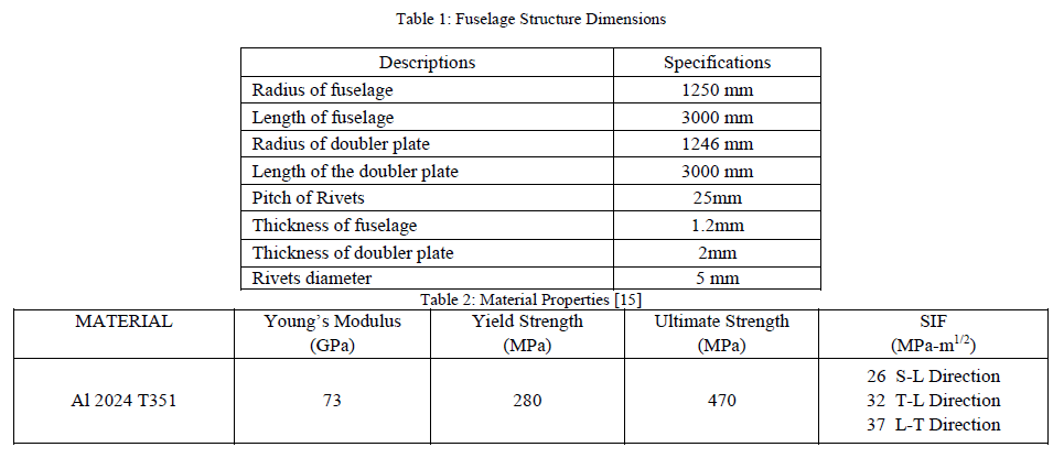
The current study includes a panel which represents the fuselage splice joint. The fuselage splice joint is a location where it experiences the uniform stress field at many rivet locations in a row. The probability of fatigue cracks initiation at many rivet locations simultaneously is more at splice joint. This paper has relevance in the structural integrity evaluation of aging transport aircrafts structural segment due to multisite damage.Finite element analysis of the Fuselage segment will be carried out to obtain the stress distribution near the joint. Fatigue cracks will emanate from the rivet holes simultaneously as they experience identical stresses due to internal pressure. In service the cracks in the fuselage will grow due to pressurization loading cycle (the difference in internal pressure and the atmospheric pressure at various altitudes). This study reveals the failure mechanics of the net section between the two advancing crack tips.There are two competing mechanism of failure; Failure due to fracture and Failure due to net section yielding (plastic collapse). The mode of failure will depend on which of the above two occurs at a lower load. The stress intensity factor calculations are carried out by using Modified Virtual Crack Closure Integral (MVCCI) method. The stress analysis is done using Nastran & Patran. The results were in compatible.
Keywords |
| Fatigue, aircraft, Fuselage, Net section, Stress intensity factor, Finite element analysis |
INTRODUCTION |
| The Boeing 737 of Aloha Airlines has drawn much attention. At an altitude of 7300 meters the aircraft lost a large part of the fuselage skin. It is a wonder that the aircraft could still continue flying to an airport. The failure was caused by a large number of cracks started at many rivet holes in the same lap joint, a phenomenon which is now generally labeled as multiple-site damage (MSD) [1], This MSD phenomenon mode of failure inspired me for this work. Aircraft is a complex engineering structure. The safety of the aircraft structure is the paramount important issue to be addressed by the designer. Multi site damage (MSD) is one of the important aspects to be studied to ensure the safety of the aircraft structure. Riveted joints are common feature in the built up airframe structure. The fatigue cracks will initiate from the locations of maximum tensile stress. The rivet-hole locations are one of the stress concentration regions. Therefore rivet locations are the most probable locations for fatigue crack initiation. |
II. CONSTRUCTION AND FORMULATION |
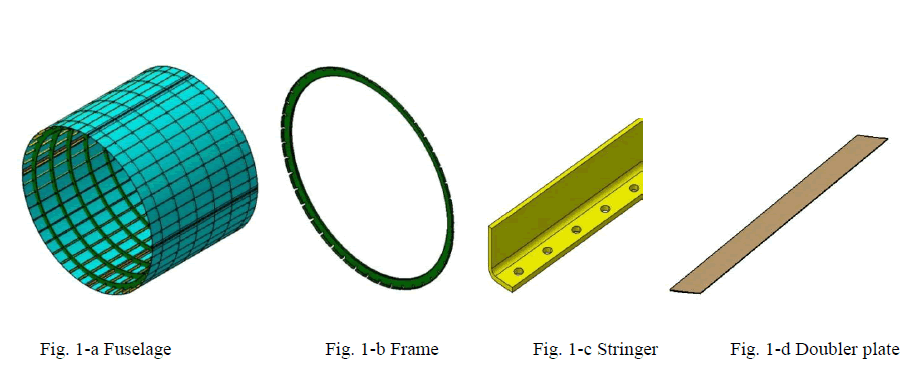
| A fuselage section (Fig. 1-a) shown below, Frame (Fig. 1-b), Stringer (Fig. 1-c) and Doubler or splice Plate (Fig. 1-d) [5], [15]. The three dimensional model is made using CATIA from the two dimensional drawings. |
 |
 |
| Load Case-Aircraft Cabin Pressurization: Aircraft are flown at high altitudes for two reasons. First, an aircraft flown at high altitude consumes less fuel for a given airspeed than it does for the same speed at a lower altitude because the aircraft is more efficient at a high altitude. Second, bad weather and turbulence may be avoided by flying in relatively smooth air above the storms. Considering the average flying altitude as 30,000 feet (Max) where the Atmospheric pressure will be around 4.4 psi and atmospheric pressure at sea level will be around 14.7 psi. The pressure variation on the fuselage ranges from 14.7 psi to 4.4 psi, i.e. in an average the differential pressure on the fuselage cabin is taken as 10 psi. |
III. ANALYSIS OF LONGITUDINAL SPLICE JOINT IN THE FUSELAGE SEGMENT |
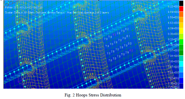
| A. FEM modeling of Fuselage Segment: After completing the geometric modeling of the fuselage segment the doubler plate is meshed first and these elements are transformed to the fuselage then using tria element connectivity is given for entire model. Finally tria and quad elements are checked and duplicate elements are also checked. Normal’s of the elements are made unidirectional. Now it is ready for applying material and elemental properties. The fuselage model is assigned with all degrees of freedom for shell elements. It implies that shell elements are completely fixed. The Beam elements are arrested for translation in z direction (Fig. 2). The fuselage is loaded with internal pressure of 10 psi. B. Post Processing: By using the marker plot randomly 10 elements are selected and hoop stress is observed shown in Fig. 2. When compared with the theoretical values its matching, the theoretical values come around 7.29 kg/mm2. |
 |
| C. Local Analysis of the Fuselage Panel: Here the fuselage skin is treated as a panel and rivets are made using respective rivet diameter instead of 1D beam element. The rivets are assigned multi point constraints and analysis is carried out to find out the maximum elemental stress and exact location of crack initiation. The geometric model is constructed as panel represents fuselage skin with dimensions 800 mm width, 250 mm height and 1.2 mm thickness. The splice joint dimensions as 100 mm width, 250 mm height and 2 mm thickness. The boundary of the fem model is depicted in Fig. 3. |
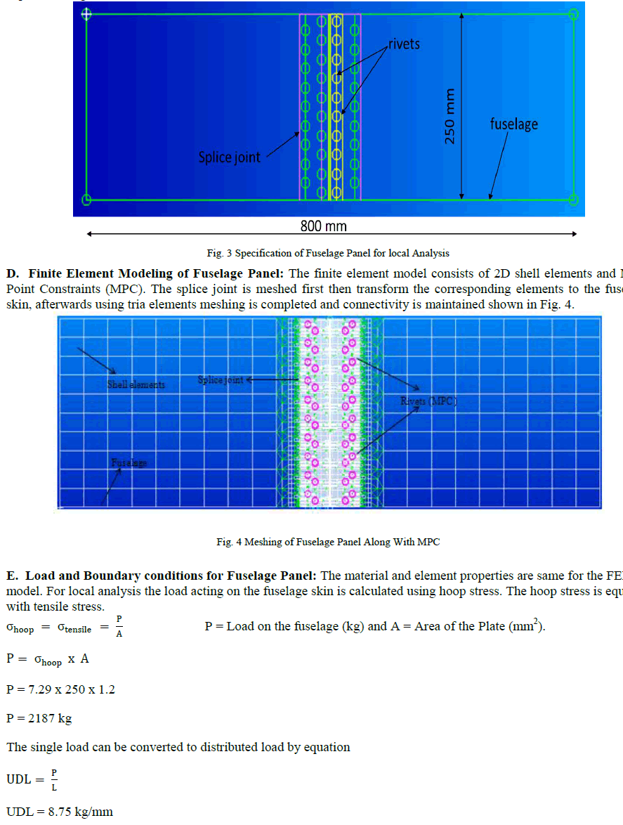 |
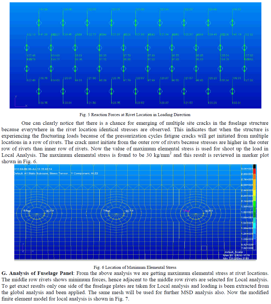
| The 8.75 kg/mm uniformly distributed load is applied .To avoid the bending of plate we are going to arrest translational motion in z direction. Now the FEM model is ready for analysis. F. Review of results for Fuselage Segment: The results are requested for grid point force balance while solving the model. After solving maximum elemental stress is noted at the rivet location and reaction forces are observed at the rivet locations in loading direction. The reaction forces are shown in Fig. 5. It is clear that the reaction forces are equal and opposite in direction and the sum of all the reaction forces will give the value of applied load. |
 |
 |
IV. CONCLUSION |
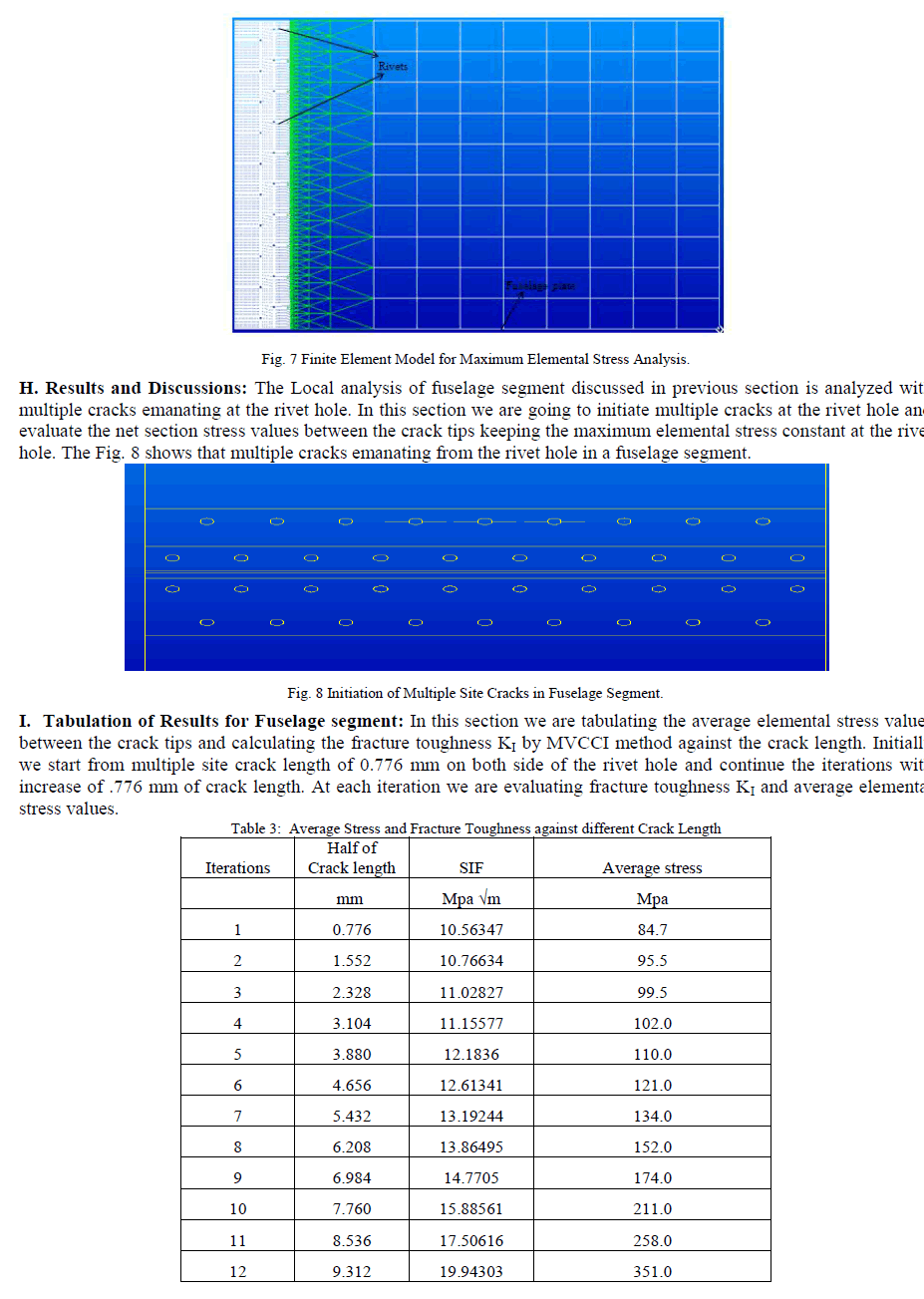
| Comparing the values from Table 2 and The Table 3, We can conclude the average stresses at the crack reaches the yield value therefore the mode of failure of fuselage panel is by Net section yielding criteria. The average elemental stress values exceed the yield strength of the material at the multiple site crack length iteration. Hence mode of fuselage failure is found is Net section yielding. The elemental stress at the crack tip will exceeds the yield strength of the material between 8.536 mm and 9.312 mm of crack length. Now comparing the values of Fracture toughness from Table 2 and from Table 3, the results reveals that the fuselage panel is not failed by Fracture criteria. The two validations of results depicts that the mode of failure of fuselage panel is by Net section yielding criteria. |
References |
|