Keywords
|
| Z-source inverter, T-Source inverter, Voltage gain, Simple boost control, Shoot-through control |
INTRODUCTION
|
| Normally the inverter converts DC to AC output. By utilizing the T-source inverter, the number of switching components and the total volume of the system can be minimized. Thus, the overall cost of the system is reduced. Tsource inverter is utilized to realize inversion and boost function in one single stage. TSI has fewer components. Due to these reason, the efficiency appreciably increase. Unlike the traditional inverter, TSI utilizes a unique impedance network that links the inverter main circuit with the DC source. The LC lattice applied in the ZSI successfully replaces the DC-DC input stage in boost-type voltage source inverters. To minimize the Z-source size, the couple inductors are designed, and the two inductors are built together on one core. The TSI topology requires a very low leakage inductance transformer which should be made with high precision. In such a way, the number of passive elements is reduced because only the transformer and the capacitor are needed. As with a conventional ZSI, the TSI can handle shoot through states when both switches in the same phase leg are turned on. The T-network is used instead of the LCnetwork for boosting the output voltage by inserting shoot through states in the PWM. T-source Inverter operating principle same as that of conventional ZSI. TSI operate in Shoot through mode and Non shoot through mode. In shootthrough mode of operation, the output voltage is boosted. In conventional method VSI, it is not possible. |
RELATED WORK
|
| The new impedance network called T-source network invented to overcome the drawbacks of the Z-source inverter. Normally Z-source inverter requires two inductance and two capacitance but T-source inverter requires a very low leakage inductance transformer which should be made with high precision. In such a way, the number of passive elements is reduced because only the transformer and the capacitor are needed so that total volume of the system can be minimized. Thus, the overall cost of the system is reduced. TSI can handle shoot through states when both switches in the same phase leg are turned on. The T-network is used instead of the LC-network for boosting the output voltage by inserting shoot through states in the PWM. T – Source Inverter operating principle same as that of conventional ZSI.All PWM Methods is used to control the T-source inverter. Here, Simple Boost Control Method is used to control the Tsource inverter. TSI operate in Shoot through mode and Non shoot through mode. In shoot-through mode of operation, the output voltage is boosted |
Z-SOURCE INVERTER
|
| A. General Description |
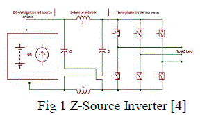
| The new impedance network has been introduced to overcome the problems of the traditional V-source and Isource inverters. It can be used in ac/dc power conversion applications. Fig.1 shows the general structure of Z-source inverter. The power source can be either in the form of voltage source or current source. Ths impedance network reqiures two inductors and two capacitors connected to each other |
| [4] ZSI provides a single-stage voltage buck-boost operation. Unique LC impedance network significantly improves the performance of the inverter. It allows shoot-through states of the inverter legs during boost operation as well open circuits of inverter legs during normal (buck) operation.[4] |
| B. Drawbacks Of ZSI Network |
| There are some disadvantages present in Z-Source impedance network and it is given below |
| ? In some applications the efficiency of Z-source inverter lower than conventional two-stage buck-boost systems |
| ? In Z-source inverter ,inductances cause over voltages during switches commutation. Hence high rating of switches is needed in Z-source inverters design |
| ? In some applications Z-source inverter produces discontinuous input current and high values of di/dt due to that LC filter is needed in input side |
T-SOURCE INVERTER
|
| A. General Description |
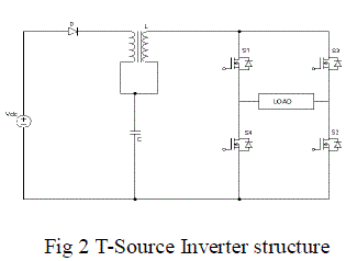
| T-source impedance network is newly introduced to overcome the problems of Z-source inverter. T-Source inverter is similar to Z-Source except the use of high frequency low leakage inductance transformer and one capacitance. It has low reactive components in compare with conventional ZSI. Due to this , the efficiency appreciably increase.The TSI topology requires a very low leakage inductance transformer which should be made with high precision. In such a way, the number of passive elements is reduced because only the transformer and the capacitor are needed. As with qZ-source inverters, the TSI topology features a common dc rail between the source and inverter, which is unlike traditional ZSI circuits. Moreover, use of a transformer with other than a 1:1 transformer ratio allows for a change of output voltage Z-source converters, as contrasted with the voltage resulting from the shoot-through index or the modulation index. |
| The features of T – Source inverter are as follows: |
| ? Low reactive components in comparison to conventional Z-source inverter. |
| ? Use of a common voltage source of the passive arrangement. |
| ? Minimize the number of switching devices |
| ? No needs of dead time. |
| ? Inductor decreases the inrush current and harmonics in the inrush current. |
| B. Principle Of Operation |
| As with a conventional ZSI, the TSI can handle shoot through states when both switches in the same phase leg are turned on. The T-Source network is used instead of the LC-network for boosting the output voltage by inserting shoot through states in the PWM. T – Source Inverter operating principle same as that of conventional ZSI. TSI operate in two modes :i) Shoot through ii) Non shoot through mode |
| i) Shoot through mode: |
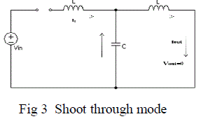
| Fig. 3 shows the equivalent circuit of T – Source Inverter in Shoot through mode operation. This shoot through zero state prohibited in traditional voltage source inverter. It can be obtained in three different ways such as shoot through via any one phase leg or combination of two phase leg. During this mode, Diode is reverse biased, separating DC link from the AC line. |
| A desired voltage can be maintained at the output by controlling the interval of shoot through state. Thus the T – Source inverter highly improves the reliability of the inverter since short circuit across any phase leg is allowed and it cannot destroy the switches in the inverter |
| (ii) Non – shoot through mode |
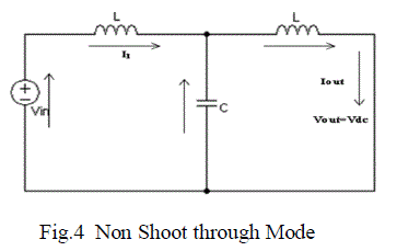
| Fig 4 shows the equivalent circuit of TSI in Non – shoot through mode operation. In this mode, the inverter bridge operate in one of traditional active states, thus acting as a current source when viewed from T – source circuit. During active state, the voltage impressed across load. The diode conduct and carry current difference between the inductor current and input DC current. Note that both the inductors have an identical current because of coupled inductors. |
| C. Design Of T – Source Inverter |
| During the design of TSI the most challenging is the estimation of values of the reactive components of the impedance network. The component values should be evaluated for the minimum input voltage of the converter, where the boost factor and the current stresses of the components become maximal. Calculation of the average current of an inductor |
 |
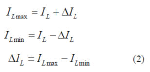
| The maximum current through the inductor occurs when the maximum shoot-through happens, which causes maximum ripple current. In our design, 60% peak-to-peak current ripple through the Z-source inductor during maximum power operation was chosen. Therefore, the allowed ripple current is ΔIL, and the maximum current through the inductor is ILmax: |
 |
| The boost factor of the input voltage is: |
 |
| where D0 is the shoot-through duty cycle: |
 |
| Calculation of required inductance of Z-source inductors: |
 |
| Where, T0 - is the shoot-through period per switching cycle |
| Calculation of required capacitance of Z-source capacitors: |
 |
PULSE WIDTH MODULATION TECHNIQUE
|
| A. Types Of PWM Techniques |
| There are two types of PWM Techniques are available namely, |
| ? Sinusoidal Pulse Width Modulation (SPWM) Technique |
| ? Modified Space Vector Modulation (MSVPWM) Technique |
| The various PWM control algorithms are |
| ? Simple Boost Control (SBC) |
| ? Maximum Boost Control (MBC) |
| ? Maximum Constant Boost Control (MCBC) |
| ? Traditional Space Vector Modulation (TSVPWM) |
| ? Modified Space Vector Modulation (MSVPWM) |
EXITSTING METHOD
|
| In this method the performance and analysis the Z-Source inverter with maximum constant boost control technique |
| A. Result and Outputs |
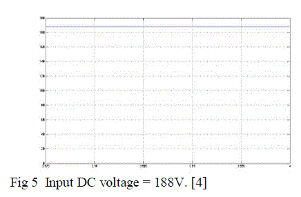
| Dc input voltage 188 is given to ZSI . The capacitor voltage is known as the average dc link voltage which remains constant about 337V and the input voltage (188V) increased (337V) and given as dc link voltage. The peak value of dc link voltage shows as input voltage across the inverter bridge circuit. |
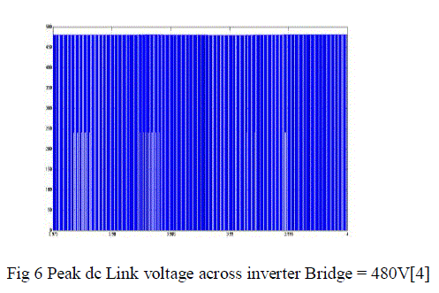
| [4] Fig 6 shows The output voltage of inverter bridge circuit . this is known as peak dc link voltage The peak dc which remains constant about 480V. |
PROPOSED METHOD
|
| In this paper the analysis of T-Source with Simple Boost Control technique is proposed. The T-source inverter is advanced impedance network than the Z-source inverter and it can be applicable in all ac & dc conversion applications. All PWM methods can be used to control T-source inverter. The simple boost control method is simple to control T-source impedance network |
| A. Simple Boost Control |
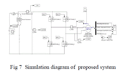
| In simple boost control, the shoot-through periods are fabricated by two straight lines which are equal or greater than the (maximum and minimum) peak values of the modulation reference sinusoidal signal. Shoot through switching pulses are generated by comparing the dc signal (with equal or greater than the peak of triangular signal) with the high frequency triangular carrier signal. |
| B. Simulation Diagram |
EXPERIMENTAL RESULTS
|
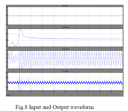
| Simulation model for single phase T-source inverter was designed by using MATLAB/ SIMULINK. Fig.8 shows the output voltage and current waveform of T-source inverter with simple boost control technique. Here, the input voltage is 100V. The output voltage is boosted up to 220V by shoot through duty ratio. In Exitsting method the peak dc link voltage 480V but using T-source network better efficiency obtained compare with Z-source inverter because of low reactive components usage. |
CONCLUSION
|
| This thesis deals with the Analysis of T-source inverter with simple boost technique for improving voltage gain . The T-source inverter overcomes the problems of the Z-source inverter and provides buck-boost operation in a single stage . The T-source impedance network produces output voltage larger than the input voltage by proper maintaining the shoot-through duty ratio, which cannot be achieved by the voltage-source inverter and current-source inverter .The T-source inverter has less passive components in compare with ZSI . All PWM methods can be used to control T-source inverter. In this thesis deals with Simple boost control technique which is used to control the T-source inverter . The output of the T-source inverter is given to the induction motor. The output voltage can be varied by varying the DC input voltage. |
Figures at a glance
|
 |
 |
 |
 |
| Figure 1 |
Figure 2 |
Figure 3 |
Figure 4 |
 |
 |
 |
 |
| Figure 5 |
Figure 6 |
Figure 7 |
Figure 8 |
|
| |
References
|
- Wei Qian, Fang ZhengPeng, and Honnyong Cha, “Trans- Z-Source Inverters” in IEEE Transactions On Power Electronics, VOL. 26, NO. 12, December 2011
- Fang ZhengPeng, Senior Member, IEEE, “Z-Source Inverter” in IEEE Transactions On Industry Applications, VOL. 39, NO. 2, March/April 2003
- Ryszard Strzelecki, MarekAdamowicz and Natalia Strzelecka, “New Type T-Source Inverter” in Proceedings on Compatibility and Power Electronics 6th International Conference-Workshop,pp.191-195, 2009
- Amol R. Sutar, Satyawan R. Jagtap, JakirhusenTamboli, “Performance Analysis of Z-source Inverter Fed Induction Motor Drive in International Journal of Scientific & Engineering Research, Volume 3, Issue 5, May-2012 ISSN 2229-5518
- CursinoBrandaoJacobina, Antonio Marcus Nogueira Lima, “Current Control for Induction Motor Drives Using Random PWM” in IEEE Transactions On Industrial Electronics, VOL. 45, NO. 5, pp.704-712, 1998
- FizatulAiniPatakor, MarizanSulaiman, Zulkifilie Ibrahim, “Comparison Performance Of Induction Motor Using SVPWM And Hysteresis Current Controller” in Journal of Theoretical and Applied Information Technology, Vol. 30 No.1,pp.10-17,2011
- Marian P. Kazmierkowski and and Luigi Malesani, “Current Control Techniques for Three-Phase Voltage-Source PWM Converters: A Survey” inIEEE Transactions On Industrial Electronics Vol. 45, No. 5,pp.691-701, 1998
- Omar Ellabban, Joeri Van Mierlo and Philippe Lataire, “Comparison between Different PWM Control Methods for Different Z Source Inverter Topologies” in Proceedings on IEEE Conference Recent Photovoltaic spec., 2008
- Papavasiliou, S.A. Papathanassiou, “Current Control of a Voltage Source Inverter connected to the Grid via LCL Filter” in IEEE Trans. on Industry Applications, Vol. 37, No. 2,pp. 229-235, 2010
- Poh Chiang Loh, MahindaVilathgamuwa, “Pulse-Width Modulation of Z-Source Inverters” in IEEE Transactions On Power Electronics, VOL. 20, NO.6, pp.1346-1355, 2005
- Poh Chiang Loh, YihRong Lim and ChernWernTeo, “Transient Modeling and Analysis of Pulse Width Modulated Z-Source Inverter” in IEEE Transactions on Power Electronics, VOL. 22, NO. 2, pp.498-507, 2007
- Sivaraman.P, A. Nirmalkumar, “ Modelling and Simulation of Photovoltaic Array fed T-Source Inverter” in International Conference on Sustainable Energy and Intelligent System ,2011
- Sivaraman.P, A. Nirmalkumar, “Analysis and Implementation of Novel TSI for High Voltage Gain Application” in International Review on Modelling and Simulations,2010
- Sivaraman.P, A. Nirmalkumar, “Analysis of T-Source Inverter with Various PWM Schemes” in European Journal of Scientific Research, Vol.71 No.2 , pp. 203-213,2012
- Thangaprakash.S, A. Krishnan, “Comparative evaluation of modified pulse width modulation schemes of Z-source inverter for various applications and demands” in IEEE Trans. on Industry Applications, Vol. 37, No. 2,pp. 299-307, 2009
- Omar Ellabban, Joeri Van Mierlo, and Philippe Lataire ,”Experimental Study of the Shoot-Through Boost Control Methods for the Z-Source nverter” in The department of Electrical Engineering and Energy Technology (ETEC), VrijeUniversiteitBrussel (VUB), 1050 Brussels, Belgium
|