Keywords
|
| Anemometers; Flow measurement; Flash evaporation technique; Peltier effect |
INTRODUCTION
|
| In recent years local cooling and electric power generation using microdevices that work based on the Peltier and Seebeck effects is a topic of growing interest. Thermoelectric cooling based on Peltier effect has the advantages of not using any moving mechanical parts, being environmental friendly, allowing integration with microelectronic circuits and being easy to control. The hot wire anemometer has been used for many years as a research tool in fluid mechanics (1-6). A hot wire anemometer usually refers to the use of a small electrically heated element placed in a fluid with the aim of measuring a property of that medium. Normally the property being measured is the velocity since these elements are sensitive to heat transfer between the element and its environment (3). |
| The originality of thiswork is to presentan anemometer operating on acompletely different principle phenomen aexploited so far. Indeed, we present an anemometerusing theobserved temperature changeson amicro-module Peltiers ubjected to air flow. |
| Measuring the temperature at the interface is a Peltier junctionwhen it is subjected to an air flow. The micro module Peltier said butterfly structure by its geometry allows maintaining butterfly wings and at room temperature to promote the Peltier effectingat thejunctionmaterials. |
| The choice of materials most commonly used for thermoelectric conversion application depends on the Seebeck coefficient, α, the thermal conductivity, K, and the electrical resistivity, ρ. For a thermoelectric device consisting of Nand P-type materials, the thermoelectric figure of merit Z. The choice of the optimum materials consists in a compromise between the three previous parameters in order to obtain the best efficiency of the thermoelectric sensor. This article describes a new sensor realized by flash evaporation technique with thermoelectric materials which have a high figure of merit Z. We worked on the development of devices allowing the velocity measurement of an air flow with good sensitivity, low power consumption for industrial application (7-10). We developed butterfly structure sensors which are constituted by a line of thermocouples. By elaborating an original geometry we investigated the sensitivity and the realization of this anemometer. |
MATERIALS AND METHODS
|
| Theflashevaporation isa technique usedto depositcomposedof materials withdifferent vapour pressuresor verydifferentthin films.The noveltyof this technique isto usea singlehot spring,butheated abovethe temperature oftheevaporation ofless volatilematerial.Variousdevicescommerciallyavailableflash evaporation. The example given isthe equipmentdeveloped byBalzers. Thisiswhat we haveusedforthedepositionofmaterials based onBi,Sb, Te, Se, and theirternary and quaternaryalloys.Whenthe crucible isat the desired temperature, thebaseis vibrated(by means of an embeddedmagnet) andthepowderrises alongthe helical groove, and then falls intothe funnelinto the crucibleand then, heated beforehand. By varyingthe intensity of thevibrationof the bottom,the rate of riseofgraindeposition rateis controlledso. We must especiallybewareof wanting toevaporatetoo quickly,because duringits evaporation, the solid grainis converted into steam, which has the effect, first toraise the pressure, andsecondly to"blow "out ofthe givengraincruciblebefore itevaporates. By varyingthe intensity of thevibrationof the bottom,the rate of riseofgraindeposition rateis controlledso. We must especiallybewareof wanting toevaporatetoo quickly,because duringits evaporation, the solid grainis converted into steam, which has the effect, first toraise the pressure, andsecondly to"blow "out ofthe givengraincruciblebefore itevaporates. The powdersare obtainedby grindingBi2Te3bulkingotsofPtype andtheN-typesubstrate on which thethin filmis depositediskapton. Kaptonsheetsare pre-annealed at 300°C for12 hours. This treatmentreducesthe elongationdue tothethermal stresseskapton. |
PELTIER EFFECT
|
| ThePeltiereffectischaracterizedbyaheatabsorption(orgeneration)bythejunctionoftwomaterialswhenacurrentpassesthroug hthejunction. Thehotwire anemometerorfilm isa system that usesthe dependence of theelectrical resistanceovertemperature.Whenplacedin aflow, means carried bythe Joule effecttoa temperature abovetheflowtemperature of thisfilm, thereis an exchangeofheatbyconvection.The exchangeis a functionof the physical propertiesof the fluid,its velocityandthe temperature differencebetweenthe heated elementand the fluid.To evaluate theheat transfercoefficientofconvection,we expressthe heat flowbyNewton's law: Ø=h.S(T-Tf) with h=λ/e |
| where his the heattransfer coefficient, the thermal conductivity of?fluid, eisthe film thickness, temperatureTfof the fluidin contactwithasolidwallarea Sand temperatureT. When thecurrent flows through thePeltiermicromoduleoflength L andcross-section S, theheat is releasedorabsorbedheatin the directionof theshuntcurrent. Theheat equation, alongthe |
 |
| where Re is the resistance of thePeltiermicromodule. Using asboundary |
| conditionsthetemperature of the junctiontemperatureandthe cold side, thesolutionof the equation is: |
 |
| The heat flowdissipatedbythe hot sectiontaking into account theconvection lossescan be written: |
 |
| The first term represents the contribution of the Peltier effect, the contribution ofthesecondconduction phenomena, thethirdinputoftheJouleeffectandthefourthterm representstheconvective losses. |
| Rt=L/λ.S is the thermal resistance of the Peltiermicro module. Thus, incorporating athermo couple on the hot face of thePeltiermicromodule, it can be shownthatthe voltage deliveredby thethermocoupleis proportionalto the heat flow. |
| Under these conditions,aconstant current,any change in theconvectiveheat transfer coefficienthwill result in avariationofthe thermocouple voltage. Hence theapplication tothe anemometer. |
RESULT AND DISCUSSION
|
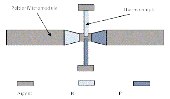
| Where α and are respectivelythe thermoelectric powerand the resistivityof the powders used. The value of havingtheannealing conditionsof the layersfor theP-typeandN-typeis to simplify themanufacturing processof the sensors.MicromodulesPeltiertellsthe"butterflystructure" (11,12)that wasmadepossiblealow contact resistanceandJouleminor. Fig.1showsthebutterflystructurewith integrateddepositedby flashevaporationthermocouple. |
| The bars ofP-typeand N-typeare notput together, butconnected by ametalelectricalandthermal shunt. The shuntandthe electrical contactsare made bydepositingbysputteringsilverNickel. In our study,we apply themicromodulePeltieranemometer. |
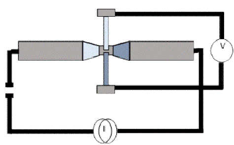
| Thefig.2represents thePeltiermicro-moduleused. it allowsus to meetthe changingtemperature on thethermal shuntbased onDC orAC currentinjected into themicro-modulePeltierknowing ΔV=α th.Δ T where α ththisthe thermoelectric powerof the thermocouple( αth=450μ V/ °C formaterials). |
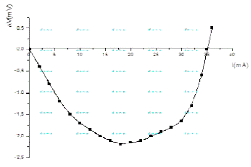
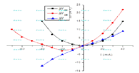
| Characterizingthisshowsthe evolution of thecurrentas a function oftemperature. Thevoltage profilethatwe foundthe thermocoupleterminalsas a function ofcurrent is givenin Fig.3. |
| On the curve, thedetectedopen circuitvoltageisequal tothe temperature differencebetweenthethermal shuntand the terminalsof the thermocouple.Theevolution of the temperaturemeasured at thethermal shuntaccordinginjected currentcan be observed, first, aloweringofthe temperatureastheinjectedcurrent increases. This corresponds tothe dominanceof the Peltiereffect on theJoule effect. |
| Then, when I= I opt= 18 mA the optimumcurrent isreached, themaximumcooling2.3°C corresponding tothe instant |
| when thePeltiereffectandJouleare equalare obtained.Finally,whenthe following behaviour:first, I > 18mA theJouletakesthe ascendancy overthe Peltier effect. Which causesatemperature riseof thethermal shunt, similar to that observedby reversing the directionof the injected current? |
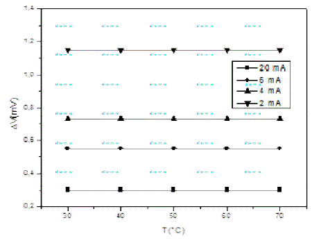
| To illustratethe insensitivity oftheintegratedeffects of ambienttemperaturethermocoupleon Fig.4, we characterized thevariationof the voltage atthe thermocoupleterminalsas a function oftheambienttemperatureT0, fordifferent streamswhen the sensor isplaced in an oven. |
| We note that thevoltage sensedby the thermocoupleat thethermal shunttakes a constantvalue forthe current injectedwhatever theambient temperature at whichthe studyis made.This shows thatthe sensor isinsensitive to ambienttemperature. This behaviouris oneof the strengths ofthe application of ourstructureasanemometerhotmovieat ambient conditions. As we haveseen, therecovered voltageacross thethermocouple?V1(proportional to the ambient temperature)proportional toflow?junctiondissipated, that is to say |
 |
| Ifwe pass analternating current inthe structure,at a sufficientlyhighfrequency todestroy thePeltiercontribution, the heat fluxis thereforefunctionof theJouledissipationand thermalconduction.Andthereby, thevoltage measured across ΔV2thermocoupleis expressed. |
 |
| Placingus in theparticular case where theinjectedcurrentis equalto the rms current, the difference in theseexpressionsgives usthe following relationship: |
 |
| ΔVdepends on thethermalconductionof heat in thePeltiermicromoduleand the contributionofthe Peltier effectat the junctionthereof. To highlightthis,we did theexperimentalsurveypresented in Fig.5. |
| We notethat the evolution of ΔVversus currentis aright.This corresponds to the theory given value Rt 223642K /W .Whereasincontrast tothisweresistance. From where Δ V= C.(αth .I.T junction) Which gives us C 0.5 . |
| Wethen placedthe sensor inan air flow, insulated from allexternal disturbances, to study theevolutionofthevoltage at thethermal shuntaccording to thespeedofair flow. Thedetected voltagedepends upon thethermalconductivityofair,theJouleeffectandthe Peltier effectat thethermal shunt. Exchangesthrough thethermal shuntare favouredbecause of itsvery small sizecomparedto the wingsof the butterfly.So thatmoreoftheair flowspeed, the higher the amount ofheatsuppliedtoor extractedfromenergysourcesmaintained byheat exchangeare important.Anemometerto lead ourstudy, we chose threecontinuous currentsupplyto highlightoursensor. |
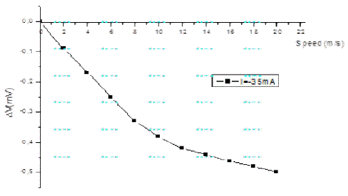
| Fig.6showstheevolutionof the voltageof the thermocoupleas a function ofair flowwhen the current I1=- 35mA , i.e. thePeltierphenomena, heat conductionandJouleneutralize. Indeed, thevoltage measuredacross thethermocoupleis zero.We find that thevoltage sensedby the thermocoupleat thethermal shuntincreases with speed. In fact, theJoule heatingofthestructure leads toheat dissipationto the surroundings. Thisisalmost completedischargetothe current injected intothestructure. This results in the increase of the temperature difference, that is to say, increasing the cooling and thermal shunt between the terminals of the thermocouple.This coolingismaximafor each valueof the flow.Dissipated in theflowmedium has, under these conditions, a maximum value. |
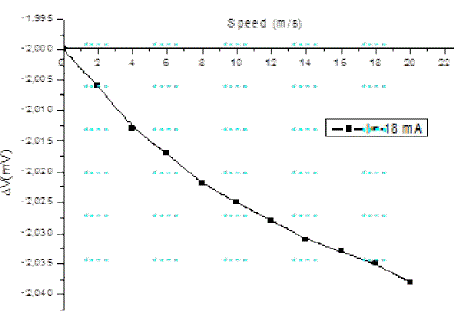
| Placingus on the Fig.7cooling thethermal shuntismaximum; placing thePeltiermicromoduleinan air flowandinjectingitintotheoptimum current, discharge of theJouleeffectprovides coolingofthethermal shuntadvantage. Sothe detected voltageallows us to havemaximum cooling. |
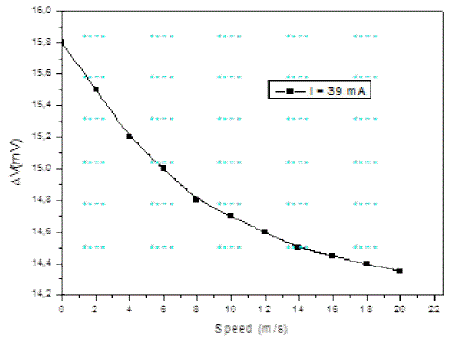
| At I3= 39mA themaximumvoltage isdetectedforthecurrentinjected. Indeed, theheating ofthermal shuntenables athermalbalancebetweenthe heat flowand heat exchangedissipatedbyconvectionwhenair flow. Indeed, onthe Fig.8, we see that the higher the speedofthe air at thesensor, the greater thedischargeenergy dissipationby the Joule effectis important.This hasthe effect of reducingthe temperature of thethermal shunttotheroom temperaturebyterminalsreferredthermocouple. |
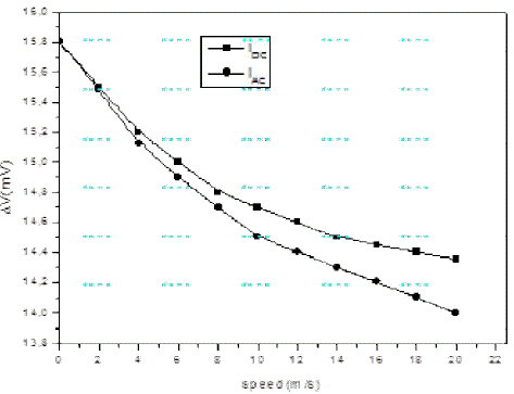
| Wethenappliedtoan alternating current sensor and in our case that the contribution of the Peltier effectintheheating of thethermal shuntmicromodulePeltierdisappears. The resultsobtained werecompared with those obtainedwithDC injection. |
| In the Fig.9its shows the twofeatures.These twocurves havethe sameallure.However,we see that atzero flow. Indeed, the thermal resistanceis large enough tomakenegligible thermalcontribution.Thus, the difference is only proportional tothe contribution ofthePeltierthermal shunt. Result in improveddrainagewithan alternating current. |
CONCLUSION
|
| The manufacturing of an anemometer by flash evaporation based on the measurement of the Peltier effect by a simple electronic device has been presented. Characterizationofthisstructurewithacontinuous feedhighlightedcoolingthermal shunt. Changes intemperaturearegiven by the measurementofthevoltage measuredacross thethermocouple. We observe amaximum coolingof2.3°Cfor amaximumcurrent of18mA. Theanemometerstudy foundevidencethe Peltier effectat themicro-modulePeltierthermalshuntandalsochanging thecoefficientof exchangebyconvection.In addition,this innovation inthe field ofair datahas the advantageof being totallyinsensitiveto temperature fluctuations, inconvenienceusuallyencountered insensorhotmovies.Finally, the originality of thisstructureopens thedoor to othertypes of sensorscurrentlyin courtStudy: thermopileconstant temperaturedetection, vacuum gauge... |
Tables at a glance
|
 |
 |
| Table 1 |
Table 2 |
|
| |
Figures at a glance
|
 |
 |
 |
 |
 |
| Figure 1 |
Figure 2 |
Figure 3 |
Figure 4 |
Figure 5 |
 |
 |
 |
 |
| Figure 6 |
Figure 7 |
Figure 8 |
Figure 9 |
|
| |
References
|
- I. Lekalis, “Calibration and signal interpretation for single and multiple hot-wire/hot-film probes”, Meas. Sci. Technol. 7, pp. 1313–1333, 1996.
- F.P. Anton, “Silicon thermal anemometry: developments and applications”, Meas. Sci. Technol. 7, pp. 1360–1377, 1996.
- F. Stella, G. Guj, D. Barbagallo, “A general approach for multiple sensors hot-wire probes”, Meas. Sci. Technol. 8, pp. 422–428, 1997.
- A. Glaniger, A. Jachimovicz, F. Kohl, R. Chabicovsky, G. Urbain, “Wide range semiconductor flow sensors”, Sens. Actuators A85, pp. 139–146, 2000.
- F. Mailly, A. Giani, R. Bonnot, P. Temple-Boyer, F. Pascal-Delannoy, A. Foucaran, A. Boyer, “Anemometer with hot platinum thin film”, Sens. Actuators A 94, pp. 32–38, 2001.
- S. Güths, D. Leclerq, E. Gaviot, “A new sensor to measure fluid velocities: the Peltier anemometer”, Meas. Sci. Technol. 8, pp. 530–535, 1997.
- Ph. Herin, P. Théry, “Measurements on the thermoelectric properties of thin layers of two metals in electrical contact. Application for designing new heat flow sensors”, Meas. Sci. Technol. 8, pp. 495– 500, 1992.
- D. Leclercq, P. Théry, “Utilization of the Peltier effect for measuring a fluid property. Application for designing new sensors”, Meas. Sci. Technol. 4, pp. 158–163,1993.
- A. Boyer, E. Cissé, “Properties of thin film thermoelectric materials: application to sensors using the Seebeck effect”, Mater. Sci. Eng. B13, pp. 103–111. 1992.
- A. Giani, A. Foucaran, A. Sackda, F. Pascal-Delannoy, G. Belleville, A. Boyer, “Thermoelectric Microconvecters Based on [(P)(Bi0.5Sb1.5Te)/(N)(Bi2Se3Te2.7)] Junctions for Use as Ther- mopile”, High Temperature–High Pressure, vol. 29, pp. 177–182, 1997.
- A. Foucaran, A. Sackda, A. Giani, F. Pascal-Delannoy, A. Boyer, “Flash evaporated layers of (Bi2Te3–Bi2Se3)(N) and (Bi2Te3– Sb2Te3)(P)”, Mater. Sci. Eng. B52, pp. 154–161, 1998.
- M. Al khalfioui*, A. Michez, A. Giani, A. Boyer, A. Foucaran, “Anemometer based on Seebeck effect”, Sens.Actuactors A 107, pp. 36-41, 2003.
|