Keywords
|
| Fast Fourier Transform (FFT), FPGA, New Distributed Arithmetic (NEDA), radix-4,modified CSLA |
INTRODUCTION
|
| Today’s electronic systems mostly run on batteries thus making the designs to be hardware efficient and power efficient. Application areas such as digital signal processing, communications, etc. employ digital systems which carryout complex functionalities. Hardware efficient and power efficient architectures for these systems are most required to achieve maximum performance. |
| Fourier analysis is named after Jean Baptiste Joseph Fourier (1768 to 1830), a French mathematician and physicist. Joseph Fourier, while studying the propagation of heat in the early 1800's, introduced the idea of a harmonic series that can describe any periodic motion regardless of its complexity. Later, the spelling of Fourier analysis gave place to Fourier transform (FT) and many methods derived from FT are proposed by researchers .In general, FT is a mathematical process that relates the measured signal to its frequency content. |
| The Fourier transform is the one of the several mathematical tools for analyzing the signals. It involves the decomposition of the signals in the frequency-domain in terms of sinusoidal or co sinusoidal components. The mathematical definition of a continuous FT (CFT) is given in the following. |
 |
| where x(t) is the original signal, X(ω) is the representation of signal in the frequency-domain, j is the imaginary number, ω is the angular frequency and t is the time index. The inverse of the continuous Fourier transform (ICFT) is defined as; |
 |
| The continuous-time periodic signals and finite-energy non-periodic signals can be defined with Fourier series representation. In addition, the discrete-time signals can be represented within finite duration in practice. An alternative transformation is called Discrete Fourier Transform (DFT) for a finite-length signal, which is discretized in frequency. The frequency range of discrete-time signals is defined over the interval between –π to π. A periodic digital signal consisted of N samples is to separate the frequency components into 2π/N radians intervals by dividing the frequencydomain. Then, Fourier series representation of the discrete-time signal will consist of N frequency components Kuo et al. (2001). The general Fourier series representation of a periodic signal (x(n)) is expressed as: |
 |
| where N is the harmonic index related with the exponentials function (e jk(2n/N)n) for k=0, 1,…,N-1, ck is the coefficients of the Fourier series.The coefficients ck are calculated as: |
 |
| The coefficients ck of Fourier series are the form of a periodic sequence of fundamental period N. The time domain spectrum of a periodic signal can be represented as periodic sequence with DFT. The frequency analysis of discretetime periodic signals (sin(nt) and cos(nt)) involves Fourier transform of the time-domain signal. DFT is defined as multiplication of N samples x(n) with N discrete frequencies. These samples are taken at discrete frequencies (ωk=2πk/N), where k=0,1...N-1, between 0≤ω≤2π. This means that X(ω) is evaluated at the successive samples by equally spaced frequencies.X(ω) is given in the following. |
 |
| DFT is a mapping between N samples x(n) of the time domain into N samples X(ω) of the frequency-domain. This gives the opportunity to compute DFT of the periodic and the finite-length signals. The frequency-domain spectrum of a periodic sequence can be re-obtained as the periodic signal by using inverse discrete-time Fourier transform (IDFT). IDFT can be defined by using the frequency samples of X(k). It is given in the following. |
 |
| IDFT shows that there is no loss information by transforming the frequency spectrum of X(k) back into the original time sequence of x(n). |
| The DFT has seen wide usage across a large number of fields; we only sketch a few examples below (see also the references at the end). All applications of the DFT depend crucially on the availability of a fast algorithm to compute discrete Fourier transforms and their inverses, a fast Fourier transform. |
| Due to increased employability of FFT inv modern electronic systems, higher radix FFTs such as radix –4, radix – 8, radix – 2K, split radix, etc. are designed for improved timing and reduced hardware. The basic difference of the mentioned methods lies in the structure of their butterfly units. |
NEDA
|
| In many digital signal processing (DSP) system,Distributed Arithmetic (DA) is used to implement multiply and accumulate (MAC) unit.DA eliminates the need of a multiplier that is used as a part of MAC unit.It implements MAC unit by pre-computing all possible products and by storing them using a read only memory (ROM). If one set of the inputs has a fixed value,ROM can be eliminated. This can be done by distributing the coefficients to the inputs of the unit. This approach is called NEw Distributed Arithmetic (NEDA). Thus, using NEDA, any MAC like unit can be implemented just by using adders and shifters. Architecture designs in use either DA approach or CORDIC unit approach to implement FFT, which require ROM as en essential unit in the design. The proposed approach is based on NEDA, which does not require any ROM thus making the design to have reduced hardware. The distribution of the coefficients is done optimally to further reduce the redundant hardware units. New Distributed Arithmetic (NEDA) technique is being used in many digital signal processing systems that require MAC unit. Transforms such as FFT, DCT, etc. have many multiplications that in turn require a number of multipliers. Implementation of such transforms using NEDA improves performance of the system in terms of speed, power and area. The mathematical derivation of NEDA is discussed as follows. Inner product calculation of two sequences may be represented as |
 |
| Where Ci are constant coefficients and Xi are varying inputs. Matrix representation of equation (7) may be given as |
 |
| Considering both Ci and Xi in 2’s complement format, they may be expressed in the form |
 |
| Where Ci= 0 or 1, k=N,N+1, … , M and Ci M is the sign bit and Ci N is the least significant bit. Substituting equation (9) in equation (8) results in the following matrix product which is modelled according to the required design. |
 |
| The matrix containing Cik is a sparse matrix, which means the values are either 0 or 1. The number of rows in C matrix defines the precision of fixed coefficients. Equation (10) is rearranged as shown below. |
 |
 |
| The W matrix consists of sums of the inputs depending on the coefficient values, in each row. An example that shows the NEDA operations is discussed below. Consider to evaluate the value of equation (12). |
 |
| Equation (13) can be expressed in the form of equation (10) as shown in equation (14). |
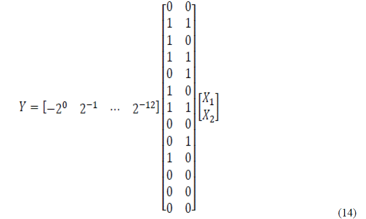 |
| Equation (14) may be rewritten as |
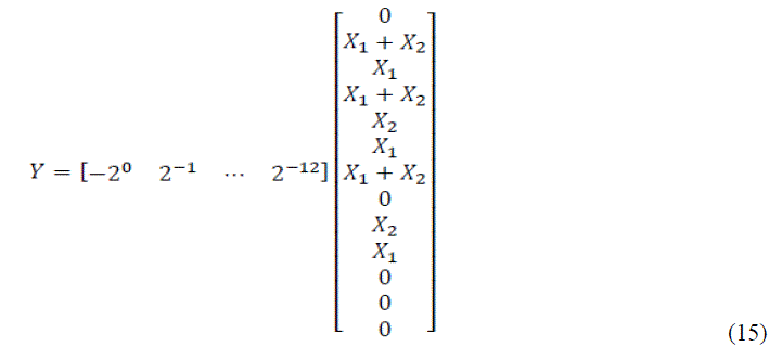 |
| Applying precise shifting, we rewrite equation (15) as |
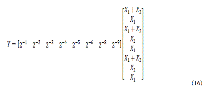 |
| Thus implementing equation (16) further reduces number of adders compared to implement equation (15). Multiplication with 2i, i-belongs to Z+ can be realized with the help of shifters. In equation (16), the first row of X matrix shifts right by 1 bit, second row by 2 bits and so on. More precisely, the shifts carried out are arithmetic right shifts. The output Y can be realized as a column matrix if we need the partial products. Thus NEDA based architecture designs have less critical path compared to traditional MAC units. |
PROPOSED RADIX-4 ALGORITHM
|
| In many applications of digital signal processing, the Discrete Fourier Transform (DFT) plays an important role.DFT has been applied in a wide range of fields such as linear filtering, spectrum analysis, digital video broadcasting and orthogonal frequency demodulation multiplexing (OFDM). The rapidly increasing demand of OFDM based applications, including modern wireless telecommunication such as LAN, needs real-time high speed computation in Fast Fourier Transform algorithm. This has made the design of FFT processor a critical requirement for the up coming wireless technology. |
| With the advent of this requirement, the study of high performance VLSI FFT architecture is likewise of increasing importance. Many different hardware architectures have been proposed for the implementation of FFT algorithms. The main concern of the design approach will be power and architectural size. Among various FFT algorithms, radix-2 FFT with Cooley-Turkey algorithm, is very popular because it makes efficient use of symmetry . Several architectures have been proposed based on Cooley- Turkey algorithm to further reduce the computation complexity, including radix-4, radix-2, and split-radix. Basically, this Fast Fourier Transform algorithm use Divide-and-Conquer approach to divide the computation recursively and then extract as many common twiddle factors as possible. The number of required real additions and multiplications is usually used to compare the efficiency of different FFT algorithms. In terms of the multiplicative comparison, the split-radix FFT is computationally better to all the other algorithms because it has most trivial multiplications. Eventually, this algorithm has a drawback because of irregular structure that leads this algorithm not suitable for implementation on digital signal processors. Structural regularity is also important in implementation of FFT algorithms on dedicated chips such as in ASIC (Application Specific Integrated Chip). Hence, radix-2 and radix-4 FFT algorithm are preferable in terms of speed and accuracy. |
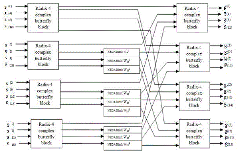
| In this paper, we have proposed the implementation of 16- point complex FFT using radix-4 method. Complex multiplications required during the process have been implemented by using NEDA. According to the radix-4 algorithm, to implement 16-point FFT, eight radix-4butterflies are required. Four radix-4 butterflies are used in the first stage and the other four being used in the second/final stage. The input is taken in normal order and the output in bitreversal order. |
| The output of each radix-4 butterfly is multiplied by the respective twiddle factors. In the shown block diagram, the first stage consists of four radix-4 butterflies. The inputs to the butterflies are s(n), s(n+4), s(n+8), s(n+12) where n is 0 for first butterfly, 1 for second butterfly, 2 for the third butterfly, and 3 for the last butterfly, all of first stage. The twiddle factors are given by W16 0, W16 q, W16 2q,W16 3q where q is 0 for first butterfly, 1 for second butterfly, 2 for third butterfly, and 3 for the last butterfly, all of first stage. The outputs of first stage are multiplied with respective twiddle factors and are given as inputs to the second stage.As proposed in our desig |
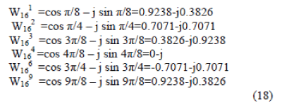
| NEDA blocks are required at the output of first stage of the 16 point FFT processor. In the second stage, 4 more radix-4 butterfly blocks are used. The first radix-4 butterfly in the second stage takes the first output of the 4 radix-4 butterfly blocks used in the first stage. The second radix-4 butterfly in the second stage takes the second output of the 4 radix-4 butterfly blocks followed by the NEDA block (if required). This process continues for the rest radix-4 butterfly blocks present in the second stage. There is no need of using any NEDA block after second stage as the twiddle factor W16 0 that is 1 is multiplied to the outputs of the second stage. The final output comes in a bit-reversal order. The advantage of using radix-4 algorithm is that it retains the simplicity of radix-2 algorithm and gives the output with lesser complexity. The NEDA block shown in the proposed block diagram does the complex multiplication of the output of the first stage and the respective twiddle factor. The twiddle factor values used here are as follows. |
 |
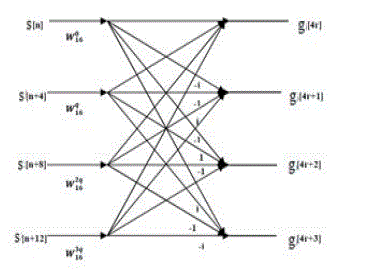
| The basic structure of the radix 4 butterfly is shown in figure 2.It has four inputs and four outputs. |
NEDA USING CARRY SELECT ADDER AND MODIFIED CARRY SELECT ADDER
|
| In the NEDA section carry select adder is used for addition.Design of area- and power-efficient high-speed data path logic systems are one of the most substantial areas of research in VLSI system design. In digital adders, the speed of addition is limited by the time required to propagate a carry through the adder. The sum for each bit position in an elementary adder is generated sequentially only after the previous bit position has been summed and a carry propagated into the next position. |
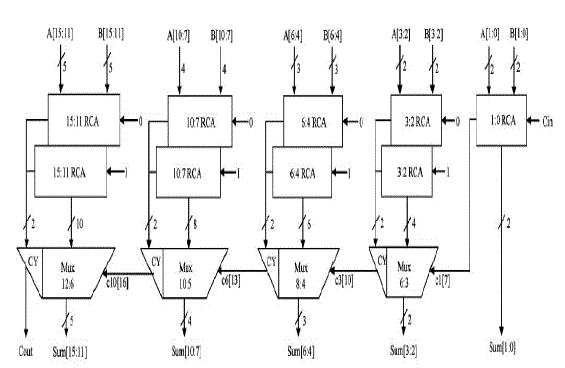
| The CSLA is used in many computational systems to alleviate the problem of carry propagation delay by independently generating multiple carries and then select a carry to generate the sum . However, the CSLA is not area efficient because it uses multiple pairs of Ripple Carry Adders (RCA) to generate partial sum and carry by considering carry input Cin=0 and Cin=1, then the final sum and carry are selected by the multiplexers (mux). |
| The structure of the 16-b regular CSLA is shown in Fig. 3. It has five groups of different size RCA. |
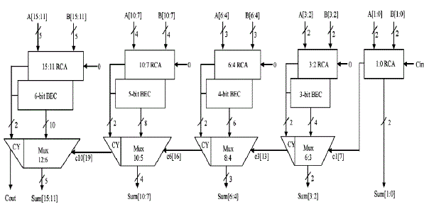
| Binary to Excess-1 Converter(BEC) is used instead of RCA with Cin=1 in the regular CSLA to achieve lower area and power consumption. The main advantage of this BEC logic comes from the lesser number of logic gates than the n-bit Full Adder (FA) structure. |
| The structure of the proposed 16-b CSLA using BEC for RCA with Cin=1 to optimize the area and power is shown in Fig. 4 |
RESULT AND DISCUSSION
|
| The synthesis report obtained from Xilinx ISE 13.2 for different Virtex FPGAs are shown in following tables.Table.I gives the device utilisation summary obtained for Virtex 6 FPGA for FFT with NEDA using CSLA and FFT with NEDA using Modified CSLA. Device utilization is less for NEDA using modified CSLA. |
| Table.II gives the power and delay obtained for Virtex 6 FPGA for FFT with NEDA using CSLA and FFT with NEDA using Modified CSLA.NEDA using modified CSLA uses less power as compared to NEDA using CSLA. |
| Table.III gives the device utilisation summary obtained for Virtex 5 FPGA for FFT with NEDA using CSLA and FFT with NEDA using Modified CSLA. |
| Table.IV gives the power and delay obtained for Virtex 5 FPGA for FFT with NEDA using CSLA and FFT with NEDA using Modified CSLA. |
| Table.V gives the device utilisation summary obtained for Virtex 4 FPGA for FFT with NEDA using CSLA and FFT with NEDA using Modified CSLA. |
| Table.VI gives the power and delay obtained for Virtex 4 FPGA for FFT with NEDA using CSLA and FFT with NEDA using Modified CSLA. |
CONCLUSION
|
| Radix 4 complex 16 point FFT core using NEDA with modified CSLA is designed. It is a ROM-less and multiplier-less method. The proposed design is efficient in terms of hardware and power consumption. Fast Fourier transform (FFT) is an efficient algorithm to compute the discrete Fourier transform and it’s inverse. A DFT decomposes a sequence of values to the components of different frequencies. This operation is useful in many fields but computing it directly from the definition is often too slow to be practical. |
| Using NEDA, any MAC like unit can be implemented just by using adders and shifters. Existent architecture designs use either DA approach or CORDIC unit approach to implement FFT, which require ROM as en essential unit in the design. The proposed approach is based on NEDA, which does not require any ROM, thus making the design to have reduced hardware. The distribution of the coefficients is done optimally to further reduce the redundant hardware units, thus reducing the hardware. The distribution of the coefficients is done optimally to further reduce the redundant hardware units. NEw Distributed Arithmetic (NEDA) technique is being used in many digital signal processing systems that require MAC unit. Transforms such as FFT, DCT, etc. have many multiplications that in turn require a number of multipliers. Implementation of such transforms using NEDA improves performance of the system in terms of speed, power and area.The proposed design is simulated by using ModelSim and synthesised by Xilinx ISE project navigator. The synthesis results show that the computation for calculating the 16 point FFT is efficient in terms of area and power using the proposed method. |
Tables at a glance
|
 |
 |
 |
| Table 1 |
Table 2 |
Table 3 |
 |
 |
 |
| Table 4 |
Table 5 |
Table 6 |
|
| |
Figures at a glance
|
 |
 |
 |
 |
| Figure 1 |
Figure 2 |
Figure 3 |
Figure 4 |
|
| |
References
|
- C. González-Concejero, V. Rodellar,“ A portable hardware design of a FFT algorithm”, Latin American Applied Research,37:78-82, 2007.
- AsmithaHaveliya, Amity University Lucknow, India “Design And Simulation Of 32- Point FFT Using Radix-2 Algorithm For FPGAImplementation” Second International Conference on Advanced Computing & Communication Technologies, 2012
- B. Ramkumar and Harish M Kittur,” Low-Power and Area-Efficient Carry Select Adder”, IEEE Transactions on Very Large Scale Integration(VLSI) Systems,VOL. 2, NO. 2,PP. 371-375, Feb.2012.
- Anumol B. Chennattucherry, Diego James, “ A Novel Approach to Reduce Area and Power for FFT Implementation”, Proc. Intl. Journal ofAdvanced Research in Electrical, Electronics and Instrumentation Engineering,vol.2,pp 130-138.
- Alban Ferizi,BernhardHoeher, Melanie Jung, Georg Fischer, and Alexander Koelpin, “Design and Implementation of a Fixed-Point Radix- 4FFT Optimized for Local Positioning in Wireless Sensor Networks,” Intl. Multi-Conf. Syst.Signals and Devices, pp. 1 – 4, Mar. 2012.
- Li Wenqi, Wang Xuan, and Sun Xiangran, “Design of Fixed-Point High- Performance FFT Processor,” Intl. Conf. Edu. Tech. and Comput.,vol. 5, pp. 139 – 143, Jun. 2010.
- M. Hasan, T. Arshan, and J.S. Thomson, “A novel coefficient ordering based low power pipelined radix-4 FFT processor for wireless LANapplications”, IEEE Trans. of Consumer Electronics: 128-134,2003.
- Stanley A.White, “Applications of Distributed Arithmetic to Digital Signal processing:A Tutorial Review,” IEEE ASSP Magazine, vol. 6,no. 3,pp. 4 – 19.
|