Keywords
|
| Zigbee, Sensor module, Coordinator module, Automation. |
INTRODUCTION
|
| these are connected together to implement, monitor and control a discrete or continuous process. Regardless of specific application needs, industrial automation networks consist of PLCs “programmable logic controllers” that communicate with remote sensors to gather data regarding such variables as pressure, temperature, vibration, sound, and strain. When the application includes a control function, PLCs act on that data by issuing commands that orchestrate processes among such actuators as relays, motors, solenoids, and valves. Sensor inputs and Controller outputs are made available to monitoring programs. Alarms are generated when process variables exceed preset levels. Security and privacy are important in the industrial automation. Reliability is an important factor where some measurable difference in implementation is required. Industrial wired networks are generally expected to deliver power to each node, as well as to carry the network signals. In many process plants, the network is also expected to be intrinsically safe, meaning that a cable break will not cause flammable gases to ignite. Wireless networks definitely have the advantage of not using wire and are inherently safe. In this paper, new method for controlling the remote sensor nodes is proposed. The real time nature of the system eliminates the delays and effects due to it. This paper is organized into 5 sections. In section I, a brief description of Industrial Automation Environment present situation and problems are introduced and a new method of designing a Wireless industrial automation system for better interactive monitoring is proposed. In section II, The Zigbee Technologies are introduced, In section III, Arm Microcontroller was described in detail. In section IV, the Coordinator Module and the Sensor Node module are discussed. In section V, the results of various operations are provided and in section V, the advantages of using the Zigbee WSN in Industrial Automation have been discussed. |
ZIGBEE TECHNILOGY
|
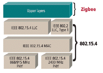
| Zig-Bee technology is a low data rate, low power consumption, low cost; wireless networking protocol targeted towards automation and remote control applications. IEEE 802.15.4 committee started working on a low data rate standard a short while ago. Zig-Bee is expected to provide low cost and low power connectivity for equipment that needs battery life as long as several months to several years but does not require data transfer rates as high as those enabled by Bluetooth. In addition, Zig-Bee can be implemented in mesh networks larger than is possible with |
| Bluetooth. Zig-Bee works in three free frequency segments, they are 2.4GHz allover international, 868MHz in Europe and 915MHz in America. |
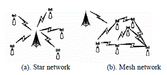
| The devices in Zig-Bee network can be divided into two kinds; they are FFD (Fully Functioned Device) and RFD (Reduced Functioned Device). The fully functioned device can be used a router, a repeater or a coordinator. A FFD can communicate with a RFD or another FFD. A RFD only used as a terminal network node. A RFD cannot direct communicate with another RFD because it has not routing and repeat function. The hardware of FFD and RFD are identical. But network layer of FFD and RFD are different. Zig-Bee network supports three network topology structure; they are mesh network, star network and cluster network. The star network is made up of a coordinator node and multi terminal network nodes. The coordinator node is used to organize network and routing information. Terminal network nodes communicate with each other through coordinator node. The cluster network is multi star network organized by a coordinator. Terminal network nodes not only communicate with coordinator node but also with every FFD node. FFD node processing routing function cannot directly communicate with each other, they can only communicate with each other via the coordinator node. The mesh network is a high reliability Ad Hoc network. The FFD nodes possessing routing function in a mesh network can communicate with each other directly, which is different from a cluster network. So the network nodes can selforganize into mesh network. Another redundancy routing path can be chosen to realize communication when one communication path goes wrong. So the reliability of communication is advanced and the delay of information transmission is shortened efficiently when mesh network is adopted. |
ARM MICROCONTROLLER
|
| The ARM is a general purpose 32-bit microprocessor, which offers high performance and very low power consumption. The ARM architecture is based on Reduced Instruction Set Computer (RISC) principles, and the instruction set and related decode mechanism are much simpler than those of micro programmed Complex Instruction Set Computers (CISC). This simplicity results in a high instruction throughput and impressive real-time interrupt response from a small and cost-effective processor core. Pipeline techniques are employed so that all parts of the processing and memory systems can operate continuously. Typically, while one instruction is being executed, its successor is being decoded, and a third instruction is being fetched from memory. The ARM processor also employs a unique architectural strategy known as Thumb, which makes it ideally suited to high-volume applications with memory restrictions, or applications where code density is an issue. The key issue behind Thumb is that of a super-reduced instruction set. Essentially, the ARM processor has two instruction sets: The standard 32-bit ARM set and A 16-bit Thumb set. The Thumb set’s 16-bit instruction length allows it to approach twice the density of standard ARM code while retaining most of the ARM’s performance advantage over a traditional 16-bit processor using 16-bit registers. This is possible because Thumb code operates on the same 32-bit register set as ARM code. Thumb code is able to provide up to 65 % of the code size of ARM, and 160 % of the performance of an equivalent ARM processor connected to a 16-bit memory system. |
| Fast general purpose parallel I/O (GPIO) |
| Device pins that are not connected to a specific peripheral function are controlled by the GPIO registers. Pins may be dynamically configured as inputs or outputs. Separate registers allow setting or clearing any number of outputs simultaneously. The value of the output register may be read back, as well as the current state of the port pins. |
| • GPIO registers are relocated to the ARM local bus for the fastest possible I/O timing. |
| • Mask registers allow treating sets of port bits as a group, leaving other bits unchanged. |
| • All GPIO registers are byte addressable. |
| • Entire port value can be written in one instruction. |
| Features |
| • Bit-level set and clear registers allow a single instruction set or clear of any number of bits in one port. |
| • Direction control of individual bits. |
| • Separate control of output set and clear. |
| • All I/O default to inputs after reset. |
| ADC |
| The ARM Microcontroller contains two analog to digital converters. These converters are single 10-bit successive approximation analog to digital converters. While ADC0 has six channels, ADC1 has eight channels. Therefore, total number of available ADC inputs for ARM is 14. |
| Features |
| • 10 bit successive approximation analog to digital converter. |
| • Measurement range of 0 V to VREF (2.0 V ≤ VREF ≤ VDDA). |
| • Each converter capable of performing more than 400,000 10-bit samples per second. |
| • Every analog input has a dedicated result register to reduce interrupt overhead. |
| • Burst conversion mode for single or multiple inputs. |
| • Optional conversion on transition on input pin or timer match signal. |
| UARTs |
| The ARM Microcontroller contains two UARTs. In addition to standard transmit and receive data a line, the UART1 also provides a full modem control handshake interface. It introduces a fractional baud rate generator for both UARTs, enabling these microcontrollers to achieve standard baud rates such as 115200 with any crystal frequency above 2 MHz. In addition, auto-CTS/RTS flow-control functions are fully implemented in hardware. |
| Features: |
| 16 byte Receive and Transmit FIFOs. |
| • Register locations conform to ‘550 industry standard. |
| • Receiver FIFO triggers points at 1, 4, 8, and 14 bytes |
| • Built-in fractional baud rate generator covering wide range of baud rates without a need for external crystals of particular values. |
| • Transmission FIFO control enables implementation of software (XON/XOFF) flow control on both UARTs. |
| • LPC2144/46/48 UART1 equipped with standard modem interface signals. This module also provides full support for hardware flow control (auto-CTS/RTS). |
WIRELESS INDUSTRIAL AUTOMATION SYSTEM
|
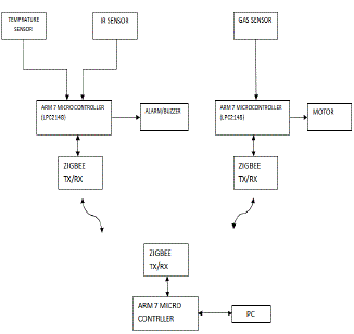
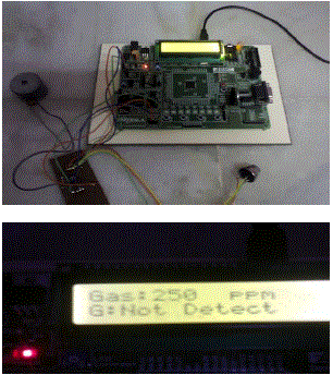
| The architecture of the Wireless industrial automation system is shown in the Figure. The system consists of the coordinator as ARM9. It is connected to the user network through the TCP/IP. This coordinator module is responsible for collecting the data from the sensor nodes and for real time monitoring. The Zigbee modules communicate with the coordinator on the server side through the RS232 cable and with the node controller on the client side. The Zigbee module plays a key role in collecting the real time data from the sensor nodes and sending and receiving the data. The Node controller at the sensor node collects the data from different sensors are sends the data to the coordinator on demand. It continuously monitors the values of the sensors with the predefined threshold values and keeps them in track in case of any deviation from the predefined values. It performs the different controlling operations when those values exceeds like it will turns off the relay connection, alarms the buzzer etc. It will display the typical values of the sensor readings on the LCD. In the sensor module, the microcontroller was initialized and also the display unit also initialized. The microcontroller start collecting data after initializing and the data or values was displayed in the LCD display. If the values are exceeded the preset levels the arm controller detects the deviation between the values and it will switch on the Buzzer/Motor which is interfaced to it. |
CONCLUSION AND FUTURE WORK
|
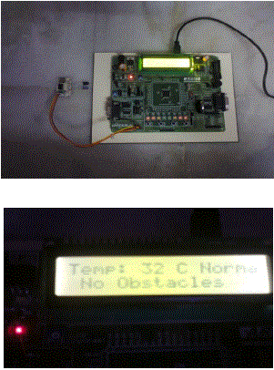
| In the present work, the sensor modules are successfully created by interfacing the sensors with the ARM7 controller. The data or values received from the sensors were displayed on the 16X2 LCD display and also controlling the corresponding devices according to the plant operation based on the received data. In future, have to develop the coordinator module and send the data collected from the sensor module to coordinator module using Zig-Bee wireless transmission. |
Figures at a glance
|
 |
 |
 |
 |
 |
| Figure 1 |
Figure 2 |
Figure 3 |
Figure 4 |
Figure 5 |
|
| |
References
|
- Research on ZigBee Wireless Sensors Network Based on ModBus Protocol, SciRes,Wireless Sensor Network, 2009, 1, 1-60.
- ZigBee Alliance, ZigBee Specification [Z], http://www. ZigBee. org.
- L. T. Cao, W. Jiang, and Z. L. Zhang, “Networked wireless meter reading system based on ZigBee technology,” Control and DecisionConference, Chinese, pp. 3455-3460, 2008.
- W. K. Park, C. S. Choi, J. Han, and I. Han, “Design and implementation of ZigBee based URC applicable to legacy home appliances,” ConsumerElectronics, ISCE 2007, IEEE International Symposium, pp. 1-6, 2007.
- Y. M. Zhou, X. L. Yang, X. S. Guo, M. G. Zhou, and L. R. Wang, “A design of greenhouse monitoring & control system based on ZigBeewireless sensor network,” Wireless Communications, Networking and Mobile Computing, WiCom 2007, International Conference, pp. 2563- 2567,2007.
|